ex-Troop Sleeper Baggage Cars – Part 3: Plugging windows

The next step with these cars involves plating over the carbody vents and the unwanted windows. The upper vents were all plated over on these cars, but the windows varied from car to car, and were done later. Up until the late 1960s and probably into the early 1970s, the cars all would have had their original windows still. In the 1970s however, some of the cars started to have windows blanked out and plated over when they received a full shopping.

The car I’m currently working on represents AC 306 (ex-AC 205, ex-US Army 7883). Photos I’ve collected from various sources online show that on one side of the car, 3 windows (2 to the right and 1 to the left of the baggage door) were plated over, while on the opposite side, only one window to the right of the door was plated.

Note that the windows I’m referring to here are all in the first double pair of windows; the original troop sleepers have a single window on either side of the original entry door, but both of these windows and the original man door are overlapping with the space where the baggage car door will go. Those windows will need to be completely gone, not just plated over with the frame still in place. That’s a little bit more involved, so I’m leaving that until later.

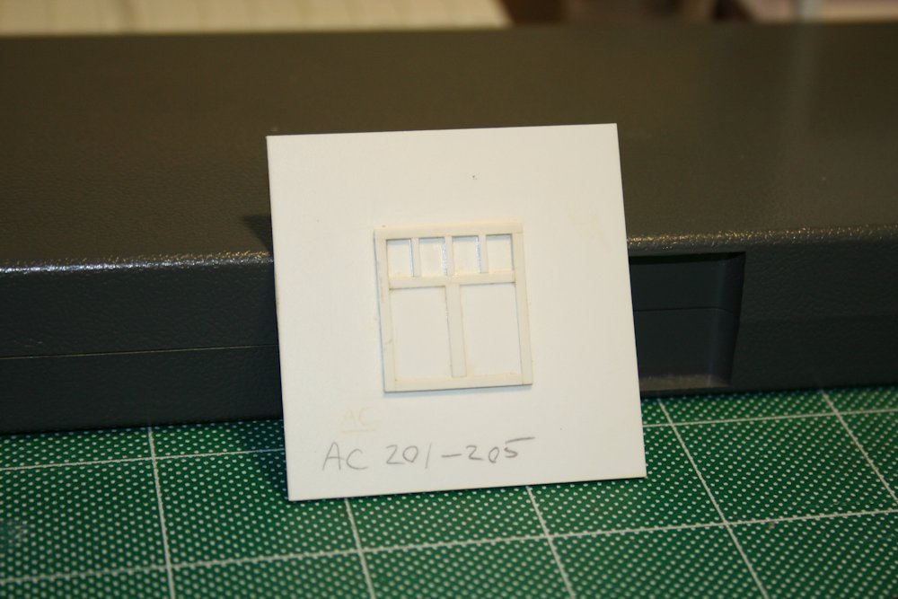
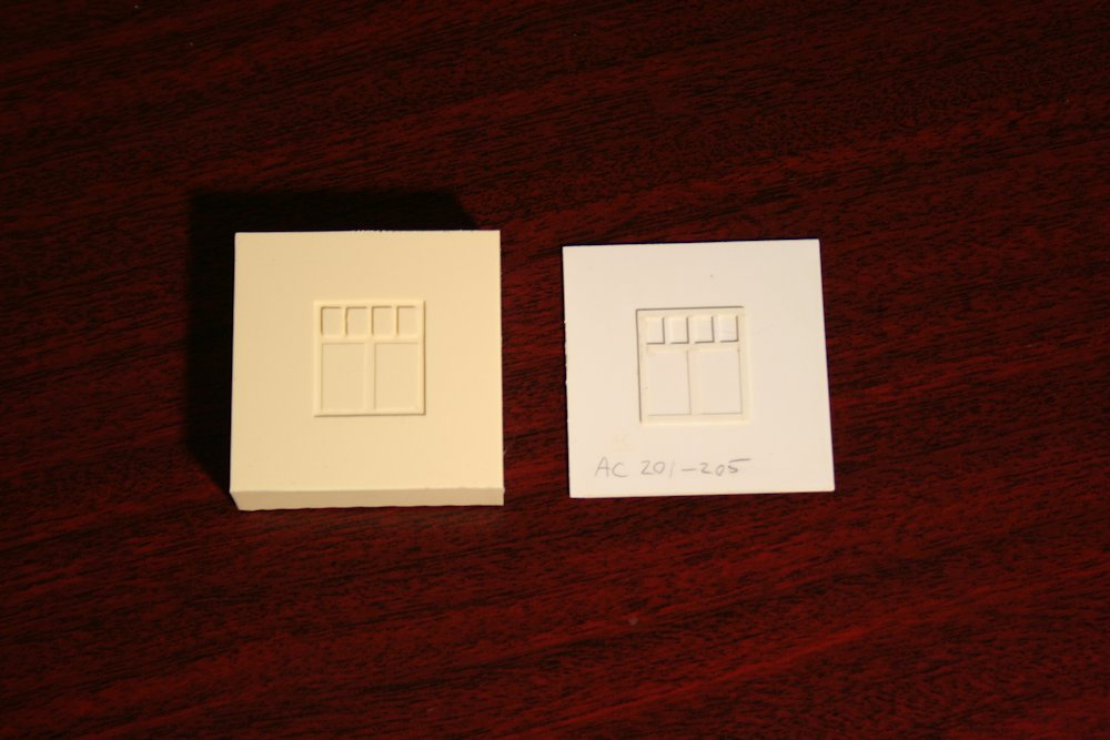
I plated the required windows quite simply by cutting rectangles of .010″ styrene sheet to fit the window openings. (Actually I cut this just slightly oversize and then carefully file down the edges so that it fits in perfectly.) When you look at the windows on the model, you can see the riveted frame around the window, and then an inset window sash, which on the rear car would have been the moveable part of the window. To plate over the window, I just cut the plate to fit just inside the outer frame, and lay down on top of the recessed sash. The .010″ thickness of the styrene sheet set on top of the recessed sash perfectly represents the plated over opening.

IMG_7186

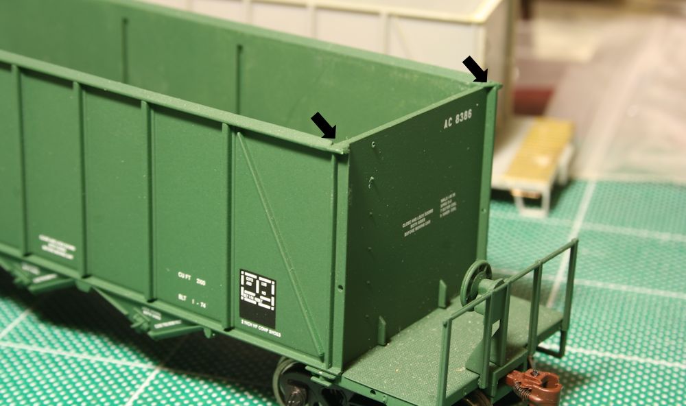
Car with upper vents and two windows at left plated over. The two windows at right will remain open and receive the original kit window glass pieces when the car is fully completed.

Similarly the vents along the top of the car body were also plugged with .010″ material but in this case their narrow width meant a 010″x.080″ strip cut to length will fit perfectly in the vent opening. Again the recessed depth is such that a .010″ strip is almost perfectly flush.

That takes care of the easy part of the car side modifications; cutting out the door, removing the single windows and smoothing everything up again will be considerably more invasive surgery.

ex-Troop Sleeper Baggage Cars – Part 2: Doors

The doors for these cars was an interesting scratchbuild project. It’s been a while since I worked out the measurements, but I was able to come up with something that looks pretty good. Here’s my drawing from my notes:

baggagedoor

Measured construction drawing of the baggage car door.

The scratchbuilt door master consists of a .020″ styrene door blank with the trimming made from scale 1″x6″ strip (except for the centre vertical that divides the lower part of the door into 2 panels with is a little wider – 1″x8″. Working carefully and measuring with my dial calipers, the trim was fixed by applying liquid styrene cement with a fine brush. My favourite here is the Testors liquid plastic cement. I highly recommend against Plastruct’s Plastic Weld in this application as I’ve found it to leave a nasty surface residue when used on styrene.

To get a nice clean upper window, I applied the trimming to the door blank before cutting out the opening. I don’t remember doing the cutting anymore, but the best approach would be to drill out the corners and then play “connect-the-dots” to cut out the rough opening. What I definitely do remember is carefully opening up the window opening with a series of fine needle files, filing the opening even with the 1×6 trim strips.

Since I knew I wanted to probably make more than one of these cars, I planned on making one door master which I could then make molds from to cast several copies in resin. The door blank was therefore cemented to a piece of .060″ styrene backing.

The window mullins were added after the door was cemented to the backing plate. This ensured that they were nice and flush. The mullins are .030x.040″ strips, laying on their wide side to match the ~.030 thickness of the .020″ door + 1×6 (.011″x.066″) trimming. These should be evenly spaced. (I didn’t keep notes for this spacing, but measuring the door master shows each window pane to be an average of .145″ wide (within a variance of .005″, well within a margin of error and not detectable by the eye).

IMG_1015

Finished door master.

Following the completion of the master, I was able to create the rubber mold from the master and use it to cast several copies of the door. I now have more than enough doors to do several cars.

IMG_1249

Rubber mold and scratchbuilt door master.

ex-Troop Sleeper Baggage Cars – Part 1: Background

In 1949, the Algoma Central began to replace their older 1914-built wooden passenger coaches with “new” secondhand steel cars acquired from the United States. (Ironically the coaches acquired from the D&RGW were actually older than the wood cars they were replacing!) Included in the AC’s acquisitions were five surplus troop sleeper cars from the US Army.

These cars were built during World War II by Pullman-Standard, and following the end of the war, many of them ended up on railways all over the continent as they became surplus, many of them rebuilt as baggage or express cars or work service bunk cars. (The Alaska Railroad had perhaps the most interesting conversions, chopping up pairs of old troop sleepers and turning them into 50′ high-cube boxcars!) The five acquired by the ACR were rebuilt as baggage cars, initially numbered AC 201-205 and painted in the ACR’s then-current dark green scheme.

These cars were rebuilt with a sliding baggage door and remained in baggage service for many years. One car, AC 204, was later rebuilt to steam generator car AC 76 in 1952 following the dieselization of the railway. The ACR also built 4 more home-built steam generator cars on the frames of old 3100 series boxcars. (No original ACR locomotives were ever equipped with steam generators. The ACR preferred the flexibility of multi-service locomotives and stand-alone steam generator cars were built to heat the passenger trains.)

In 1981 the ACR’s baggage cars were all renumbered into the 300 series to make room in the numbering for the new AC 200-205 series GP38-2 locomotives. The remaining troop sleeper cars became AC 303-306. Since my modeling time frame is 1985, this is the series my cars will be numbered within.

Over the years, windows on several of the cars were plated over. This seemed to vary a bit between the different cars, so working from photos is essential.

Most of these cars were still painted in the ACR’s handsome 1955 maroon and grey colour scheme in the 1980s. One exception was AC 306, which got painted into the 1974 silver scheme with maroon name band, but never actually received the Algoma Central lettering along the top, just the road numbers on the corners of the car. That’s just so silly, it needs to be modeled.

Here’s a link to a Ted Ellis photo of AC 205 (later AC 306) in 1979 in the silver colours:

http://algomacentral.railfan.net/images/AlgoCenRy/AC_205_Hawk_12-26-1979.jpg

And AC 303, looking a little the worse for wear, in the late 1980s still in the 1960s maroon and grey colours:

http://algomacentral.railfan.net/images/AlgoCenRy/AC_303_Hawk_Jct_6-19-1987.jpg

And lastly, a 1979 shot of steam generator AC 76, coupled to AC 74, one of the home-built generator cars just out of frame:

http://algomacentral.railfan.net/images/AlgoCenRy/AC_76_Steelton_12-30-1979.jpg

In HO scale, Walthers has produced a model of the Pullman-Standard troop sleeper car, which can be modified in much the similar fashion to the prototype in order to model these AC cars. Windows and vents will need to be plugged, enlarged door openings cut out and the doors scratchbuilt.

I’ve completed the doors and I’ve been working away on one of the Walthers cars to convert it into baggage car #306; ultimately I’d like to do the steam generator car 76 and possibly one more baggage car for a nicely rounded fleet.

Next: Scratchbuilding the baggage doors.

AC 8201-8500 series hoppers – Part 2: Interior and Top Chord

So in my previous post, I introduced this project and the prototype for these cars, 300 cars built by NSC to an Ortner design in 1974-75. Walthers makes an HO model of the Ortner design, which makes a convenient start to this project. Of course there are some details, both major and minor, that differ between the Walthers model and the AC prototype cars.

IMG_6612

Stock Walthers model without the hokey included aggregate load.

The biggest change that needs to happen is that the AC cars have tubular V-bracing between the bays, not the solid bulkheads that the model has. This takes a little bit of work, but is not difficult, and you’ll agree this makes a huge difference in appearance.

If you only want to do minimum changes or detailing to turn the Walthers car into a reasonably accurate AC car, this is the change to make. Also, since the insides of the cars were unpainted steel, this change can be done on a factory painted car while completely preserving the factory lettering, as the inside of the car should be masked and repainted a rusty colour.

The first step is the easiest, just take out the removeable bulkhead pieces and throw them away. (Or, toss them in the scrapbox. A good model railroader is a pack rat; you never know when that oddball useless leftover part now can be repurposed for something completely unintended later. Or at the very least chopped up into smaller pieces or used as part of a steel scrap load or junkyard scene.) Then I fill the holes left behind with modeling putty. Most of the cars I’ve been working on so far I’ve filled the holes using either Tamiya or Squadron putties. Other modelers also recommend Bondo putty from the automotive department, and I’ll probably try that in the future. Canadian Tire is a lot more convenient than the local hobby shops that are an hour+ away.

SAMSUNG DIGIMAX 360

Several cars in progress.

Once the body putty has had a day to cure, I file it down even with the inside surface of the sides and sand it smooth with progressively finer sandpapers. Once again the automotive aisle at Canadian Tire is rather handy here as a source for 1000+ grit finishing/polishing sandpapers to get a nice smooth interior side.

Smoothing out the bottom of the bays is a bit more tricky with the angled geometries, so I just did the best I could. A sanding stick from the hobby shop gets a good start here.

sandstick1

I used a sanding stick like this one on the inside of the bays.

Now, before I move on to installing the interior bracing, I finish cleaning up the top of the car body. (Or this part can really be done first.) The AC cars have an overhanging lip over the top of the car end that the model doesn’t have. I modeled this simply using an HO scale 2″x6″ styrene strip across the top of the end. First, however, two little angle pieces need to be carved off the top of the corners on the model and filed flush with the top of the end, as indicated in the below photo marked with arrows:

IMG_6983

Remove corner detail on top surface at points indicated to allow 2×6 header to be installed.

Once this detail is removed and smoothed down, the end cap is installed. I simply cut a piece of styrene 2×6 to length and cement it to the top of the edge. Once the end cap has been installed and the cement has set, I file down the angled top chord on the model flush all the way around with the top of the 2×6 end cap.

IMG_6986

End cap installed. End handgrabs are partially installed on this car.

Once the sides are finished, the interior bracing can be installed.

I made the braces from .040″ brass rod/wire. The rod is cut to length (approx. 1.20″) and I file one end off at an acute angle so that it rests properly against the side. Test fit this several times before glueing in place.

I drilled a small hole right next the the centre sill of the car between the bays to accept the bottom end of the brace. Then I simply use a drop of CA glue to secure both ends of the brace.

IMG_6618

Interior bracing.

AC 8201-8500 series hoppers – Part 1A: Ballast variation

S3600332.jpg

AC 8331 at Steelton Yard in 2004. Chris vanderHeide photo.

One interesting variation on these cars was a series of 10 cars, AC 8330-8339 that were rebuilt in the early 1990s with side-discharge gates suitable for ballast service.*

You can see the marks on the side of the car where the modified slope sheets have been welded to the sides, so you can see how the inside of the car peaks in the middle.

This would certainly be a neat variation to model, and an interesting kitbash, although this is several years outside of my modeling time frame of 1985.

Has anyone reading this blog ever modeled a similar sort of ballast service rebuild?

*I’ve seen video however from the early-mid 1990s of a couple of these rebuilds mixed right in with other hoppers on the branch train to Wawa/Michipicoten. It seems they were still used in regular service when not used for ballast service.