A few more from the collection. This batch is all related to the Michipicoten subdivision branchline west of Hawk Junction.
The Michipicoten branch runs 26 miles from Hawk Junction west to Wawa and the harbour on Lake Superior at Michipicoten. Primarily serving the Algoma Ore Properties (a subsidiary of Algoma Steel) iron mines and sinter plant at Wawa, this line was the domain of the ore trains.
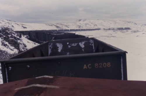
East of Wawa, winter 1980-81. Photographer unknown. Chris vanderHeide collection.
An empty ore train westbound between Hawk Junction and Wawa. East of Wawa there is a significant area where the landscape has been ravaged by the fallout of nearly a century of iron ore processing in the area. Those familiar with north-central Ontario will be aware of the similar treeless blackened landscape that made the Sudbury region [in]famous before INCO built the “super-stack” there to disperse (and thereby dilute) emissions over a larger area, and a concerted environmental remediation program was undertaken.
Here we see the ore train snaking through the rocky terrain of the treeless zone. The winter contrast of white snow against the black rocks only increases the starkness of the scene. I guess on the plus side, you get a pretty good view of the entire train, which isn’t very common on the remote lines twisting their way through the northern Ontario forests.
Look closely and note in particular the first four cars of the train – not ore hoppers but empty flatcars and a gondola for pulpwood loading at a log spur west of Wawa.
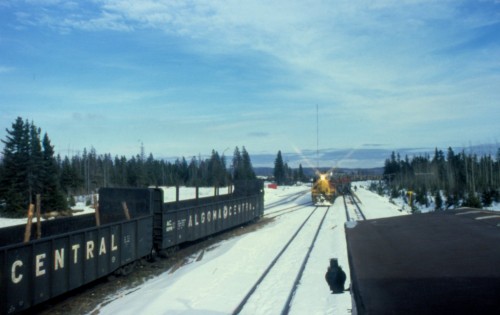
This location can be deduced to be Trembley, a siding approximately 3-4 miles west of Wawa. The timetable additionally lists two loading spurs at Trembley, one operated by Abitibi Paper (later St. Marys Paper) and the other by Newaygo Forest Products (a company that also had significant operations at Mosher and Mead on the Northern Subdivision).
Close inspection of the photo shows one of the spurs curving off far in the background to the left of the engines of the train. Based on the sequence of slides in this batch, and also comparing the layout to the traces left behind and visible on overhead satellite imagery, this photo is taken at the east end of Trembley siding from the caboose of the same train as the ore train seen above. The train is westbound to Michipicoten harbour and standing on the main track at Trembley. The engines visible in this photo are NOT from the same train however. Close inspection of both photos shows a pair of SD40 type locomotives on the head of the ore train, and there are at least 3 GP7 locomotives on the pulpwood extra seen here. (Note that timetables through the 1970s and ’80s did not list any regular trains on the branch, and all trains were run as extras.)
While the above photo at first glance may appear to show an arriving train pulling into the siding, there are a number of things that don’t make sense about that, not the least of which is that it appears to be showing a *loaded* train of pulpwood arriving from the east, and pulpwood loads should be heading back in that direction. Clearly this train was likely already here and waiting in the siding for the arrival of “our” train and has resumed actively switching the Abitibi spur in the distance, while our train has stopped on the main track to set off those 4 empty cars for pulpwood loading seen at the front of the train in the first photograph.
The branch is mostly known for the ore related traffic, and solid trains of hoppers, but this photo really shows the scale of pulpwood operations here; clearly there was enough traffic to be running both a pulpwood extra and an ore extra (which also had 4 more empty cars to drop off for pulpwood loading!) The 1978 Time Table lists car capacities of the Abitibi and Newaygo spurs at Trembley at 45 and 24 cars, respectively (at 50′ per car), and in addition to the 44 car passing siding, instead of a car capacity in the house track column is the notation “Yard”, suggesting the presence of perhaps two or more side tracks for car storage in addition to the identified customer spurs. This definitely expands the operational possibilities on the branch line, and for pulpwood loads in general.
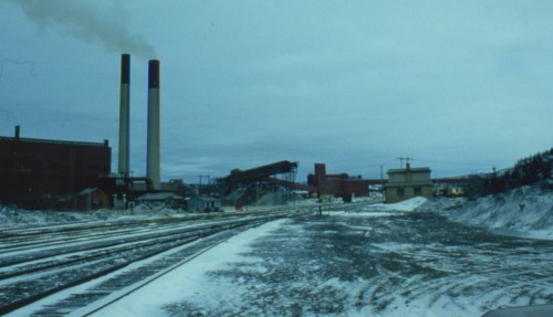
Wawa, winter 1980-81. Photographer unknown. Chris vanderHeide collection.
Wawa. The primary raison d’être of the Michipicoten branch of the Algoma Central Railway was to serve the iron mining of the Wawa area. The mining industry in the area has had a rocky history, with various operations stopping and re-starting in the early part of the 20th century.
From its incorporation in 1899, the Algoma Central was built to move iron ore from a large deposit discovered near Wawa to a harbour built at Michipicoten Bay on Lake Superior. The harbour featured a elaborate wooden ore dock and a commercial dock where passenger boats called and other ships loaded pulpwood. Ore and pulpwood was shipped south over the lake to the various industrial interests in Sault Ste. Marie. The ACR also (slowly) pushed north from Sault Ste. Marie but the 1903 financial crash of the industrial empire of which the ACR was a part brought things to a halt with construction not beginning again until 1909. It was only in 1912 that the main line reached what is now Hawk Junction and connected Wawa to the Sault directly.
The first iron ore sintering plant at Wawa was built in 1939, and was significantly expanded several times over the next 50 years. By the 1980s, ore from the MacLeod Mine (a 2000 foot deep underground mine located adjacent to the site of the original 1899 Helen open pit mine) was delivered directly to the sinter plant via the world’s tallest single-lift conveyor belt. Here the ore was heated and blended with additives such as limestone and other ore fines brought in through the harbour at Michipicoten to upgrade the ore for the Algoma Steel blast furnaces at Sault Ste. Marie. In 1998 however, the Algoma Ore operations around Wawa were shut down, with the steel mill sourcing taconite ores from south of the border, and the sinter plant was eventually torn down. Absolutely nothing in the above photo save for the rocky terrain itself still exists today.
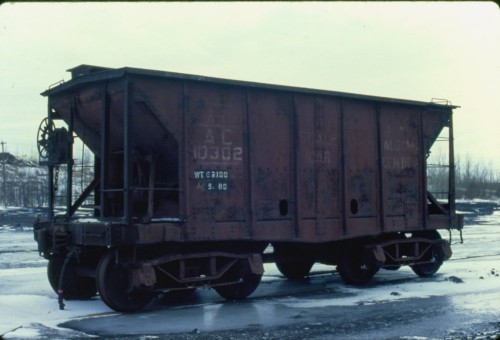
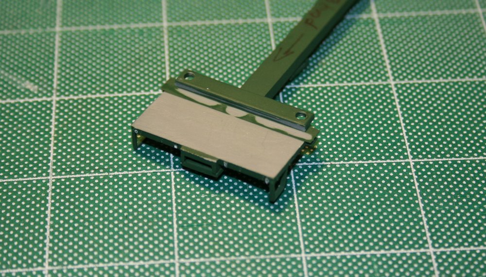
AC scale test car 10302. Wawa, winter 1980-81. Photographer unknown. Chris vanderHeide collection.
This scale test car photographed at Wawa was converted from one of the first steel hopper cars rostered by the Algoma Central. These cars were built by the Pressed Steel Car Company in 1900-1901, meaning this car was somewhere around its 80th birthday when photographed in the winter of 1980-81. Amazingly this car actually still exists today; it’s preserved at the Canadian Railway Museum in Delson, Quebec.
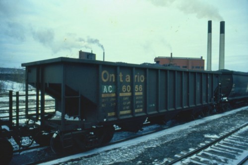
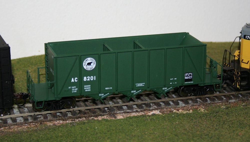
AC hopper 6056 (ex-ONT). Wawa, winter 1980-81. Photographer unknown. Chris vanderHeide collection.
From the oldest to the newest. Built in 1971 by National Steel Car for the Ontario Northland Railway, these are actually older than the 8201-8500 series rapid-discharge cars acquired new in 1974-75, but these 30 cars acquired secondhand from the ONR in 1978 were the last hoppers acquired by the Algoma Central Railway before they were absorbed by the Wisconsin Central in 1995. For several years they kept their old Ontario Northland numbers with the reporting marks re-stencilled “AC”, but around 1986 these cars were renumbered into a proper AC number series, AC 8600-8629. A check of the UMLER (computerized equipment register) shows that many of these cars are actually still in service, making them the last surviving hopper cars in AC markings.
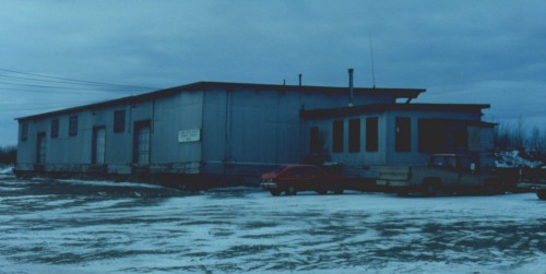
Wawa, winter 1980-81. Photographer unknown. Chris vanderHeide collection.
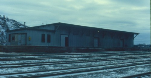
Wawa, winter 1980-81. Photographer unknown. Chris vanderHeide collection.
Express freight shed at Wawa. Front and back sides. This is pure gold for being able to model this structure. While much larger, some similarities in construction can be seen between the Wawa shed and the smaller shed at Hawk Junction, seen in the previous post.
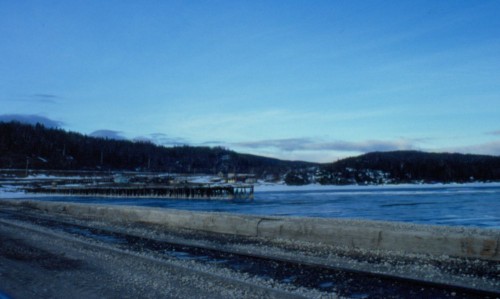
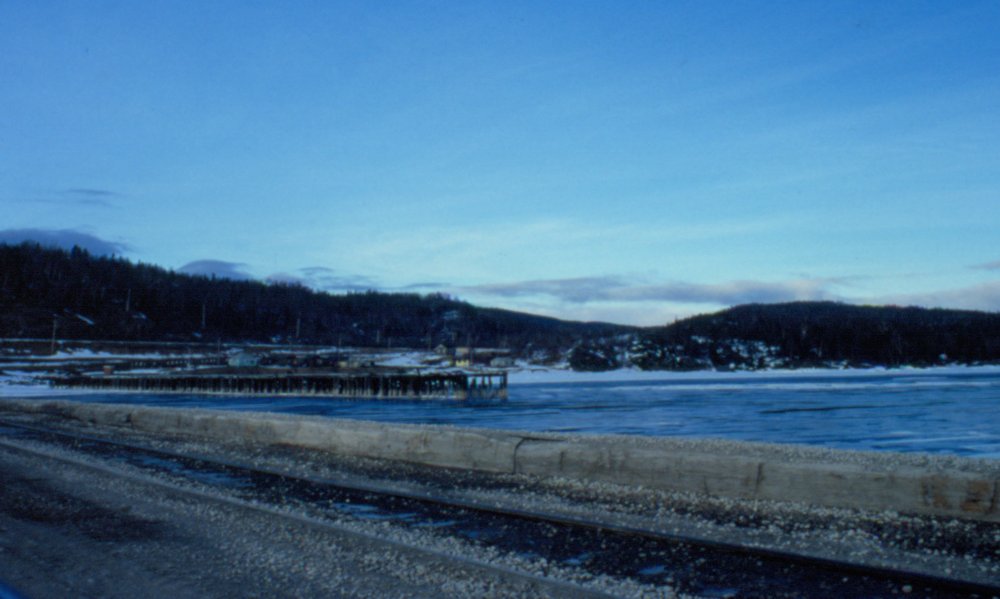
And finally, on the frozen shores of Lake Superior at Michipicoten harbour. This photo is taken from the modern dock at Michipicoten, which was built as a coal dock in 1929 (and extended in size several times over the years) to replace the original ore dock. From the 1920s to the 1960s, this was a port to bring in coal to fuel northern Ontario paper mills and also for CNR locomotive coal for northern terminals. In 1939 when the sinter plant was constructed at Wawa, an ore unloading bridge was added to tranship ore from rail to ship. It’s too bad there were no slides that showed the opposite direction, looking towards the old facilities on the coal dock – a video I have from the late 1980s shows that some remnants of the old steel work was abandoned but actually still standing at this time. By the 1980s all of the previous operations at Michipicoten had been abandoned but the dock continued to see significant traffic. Self-unloading ships depositing huge stockpiles of limestone, coke and other ore fines on the dock, and these were loaded into hoppers using large front-end loaders and shipped as required to Wawa to support the operations of the sinter plant there.
The old rotting wooden dock visible in the above photo is the remains of the original commercial dock, abandoned some time in the late 1950s or early 1960s


