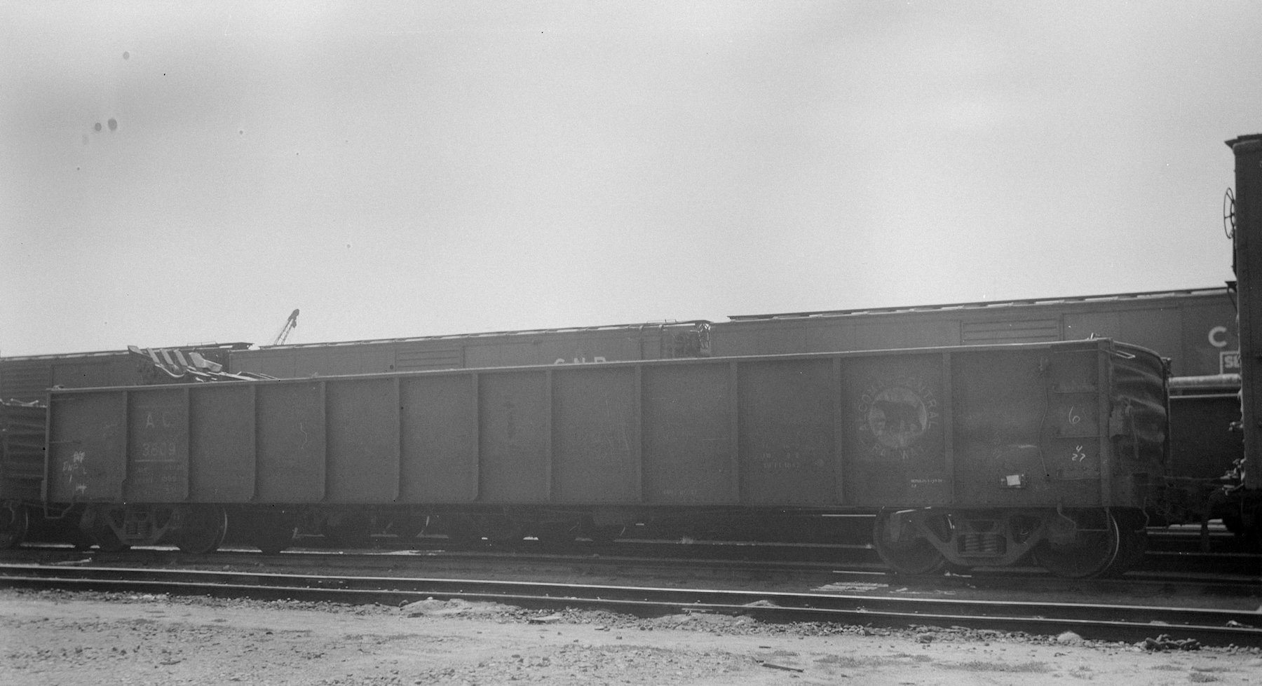
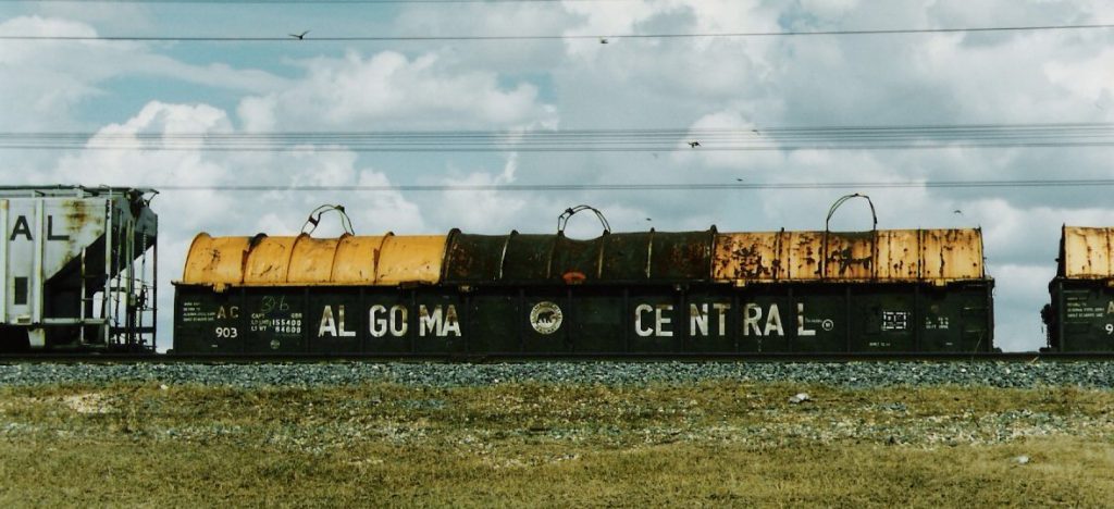
One of the interesting variations of gondolas operated by the Algoma Central was their group of 52′ gondolas modified for steel coil service. These cars were outfitted with internal wooden bunks for loading the coils of sheet steel and three piece round steel covers to protect the contents from the elements. These covers were painted bright yellow, which on top of the standard black ACR gondola made for an eye-catching appearance. (Although as the covers got banged up during handling, they began to rust quite heavily and some later photos show hoods on some cars that are almost uniformly brown.)
All told there were a total of 45 cars in this service by the mid 1980s. Roster listings are a little messy, but it appears the first 25 cars numbered 900-924 were delivered new by National Steel Car in December 1961. A total of 20 additional cars would be drawn from the 601-875 series for conversion in the late 1970s-early 1980s and renumbered 925-934 and 975-984. (Some notes in Official Railway Equipment Registers in the mid-late 1980s also show an additional 10 cars within the 601-875 series marked out as being fitted with coil bunks but not covers, and maintaining their original numbers.)
| Series | AAR Mech. | Built | Note |
| 900-924 | GBSR | 12/61 | New |
| 925-934 | GBSR | 12/57 | ex-601-875; converted between 1980-84 |
| 975-984 | GBSR | 12/57 | ex-601-875; converted 1979-80 |
As these cars are quite visually distinctive, and important to steel products service on my mid 1980s era layout, I’ve long wanted to model some of these, and have kicked around some ideas for scratchbuilding the hoods out of styrene tube, or styrene sheet wrapped around a former, but never got around to actually building any yet.
A couple of years ago however, I acquired an Elegoo Saturn 3D printer, and decided that these coil hoods might be well suited to that application. I drew up the designs from photos and was able to print out the hoods for several cars.
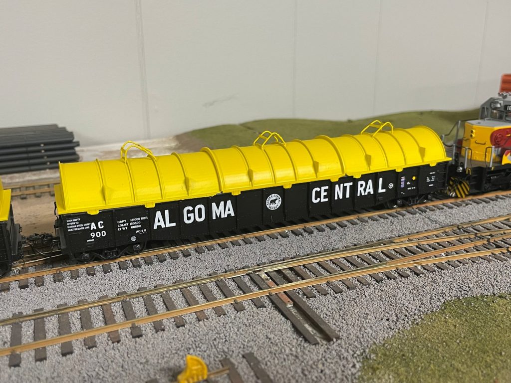
The hoods were printed in three pieces similar to the real ones, including the reinforcing ribs and stacking brackets as part of the print. The crane lifting brackets on the tops of the hoods were soldered together from brass wire and small bits cut from .005″ brass sheet.
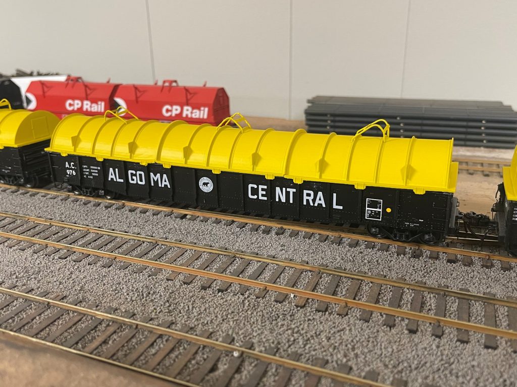
After completion, the hoods were primed and then painted yellow (Vallejo Model Air #71.002 Medium Yellow) and installed on the cars. My 52′ gondola models are all from Rapido Trains, as they are the only ones that correctly match the spacing and number of side ribs, but the hoods fit other models of 52′ gondola as well. Two cars were painted from undecorated models using decals from Precision Design Co. which match the more rounded billboard lettering style on the lower numbered 900 series cars, while the rest of the cars were factory painted Rapido cars with just renumbering into 900 series numbers, which represent nicely cars renumbered from the 601-875 series.
My fleet of AC coil steel gons now stands at seven, a respectable number which should cover my operational needs quite nicely when combined with some CN and CP coil cars. Now all that remains is some weathering, and a proper layout to run them on!