Over the long weekend and this week I’ve had the opportunity to get back into some of my modeling. One project that I’ve re-started up is starting to fabricate the scratchbuilt end racks for a few 2300 series 40′ flatcars. I started this a long time ago, building a rough test end on an old scrap Athearn flatcar, and then managed to complete the basic outline of one (actual) end before the project wandered off onto a back burner.

Test build on a scrap Athearn flatcar from the junk pile.
The test build was done to accurate dimensions overall to test the measurements, overall look and robustness of the build, although the interior framing within the end is not to scale, just thrown in for effect and to strengthen the assembly. The simple square of butt-joined styrene strip is extremely fragile, but once assembled into a whole piece with the inner bracing and the wide walls, the whole thing is actually remarkably rigid.
The test build appearing to be rather successful, it was on to start fabricating real parts, with precision cut pieces and all the inner parts located properly.

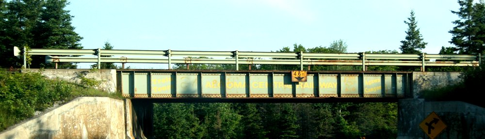
End view of AC 2358 at Frater in 1996. Blair Smith photo.
I’m lucky to have a couple of nice dead-on end shots saved in my reference files to help scale out the ends. The dimensions listed in the equipment register give the interior height of the car (from the top of the deck boards to the top of the bulkhead) as 9’0″, and an interior width of 9’7″. Scaling from the photos, the width over the outside of the two inner square posts appears to be close to or just under 4′ across, and centred. The horizontal member is a little bit above evenly half way up the end.
The deck boards on the Athearn flat however are 9’0″ across, so fashioning the ends to add to this model to kitbash one of the ACR cars will leave the width slightly narrow, and the end rack a little bit more square than prototype. (I also measured across a Tichy kit and its width is also 9’0″.) It’s not overly noticeable, though a 6″ loss over 9’6″ is about a 5.3% difference.

One partially completed end frame, and parts for a second showing rough assembly sequence.
My outer frame is made from .030x.040″ strip for the bottom and outer side posts (as the side posts will be laminated to the thickness of the sheet used for the side of the car), and .040x.040″ for the rest of the major structural members (top and middle horizontal, and inner vertical posts). Representing the Z-shaped bar stock between the two inner square posts will be an interesting challenge yet…
To ease in the measuring and cutting, I made the top and bottom horizontal members full width, so the side and inner vertical posts are all cut to the same length and cemented between the top pieces. Then the middle horizontal pieces will be cut to fit between the spaces.
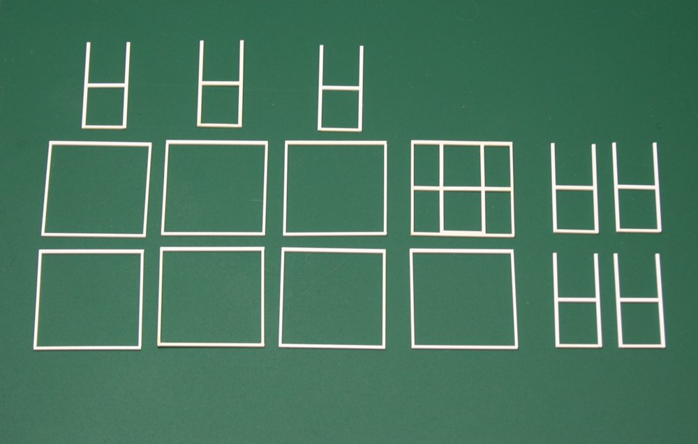
Parts and sub-assemblies for four pairs of ends.
For assembly, I glued together the outer frame first with a liquid styrene cement, using some small precision squares to keep everything aligned and square. Then the inner part of the end bracing is assembled as a unit that can be inserted into the outer frame by cutting the bottom plate from .030x.040″ strip to fit between the two posts, and the same for the horizontal part.
Once the inner frame assemblies are inserted into the outer frame and cemented together, then I’ll cut and insert the other bits of the horizontal member to finish up the basic assembly of the end frame. Then I just need to do something about the Z verticals to finish the end bracing, and move on to the sides and mounting these onto a car body.