
AC 2343 at Steelton yard, August 1996. Photo courtesy Blair Smith.
AC 2343 at Steelton yard, August 1996. Photo courtesy Blair Smith.
Over the past week or so I’ve been continuing to work away at my flatcar project, and I’ve built basic bodies for the four cars and completed the assembly of the ends, and now I have four assembled flatcars that are starting to look like an impression of the real thing.

The bodies are scratch-built from .040″ thick sheet and strip. You can see in the photo below the various parts ready for assembly: the simple flat body, a basic fishbelly underframe, and the truck bolsters are Tichy parts. The side and end sills are .040″x.125″ strip, while everything else is cut from .040″ thick sheet material.
Some weight will still need to be added to the cars along with some basic underframe detailing.

With four bodies built, the ends could be assembled and attached to the cars. With the framing for the ends previously completed, the side wings were added using .010″ thick sheet material with an .040″x.040″ reinforcing post and a .010″x.040″ top flange across the top of the side to finish everything off.

Above you can see the end details on a single car; each of the four are identical.
With the basic assembly complete, these models are really starting to look like something, but there’s still a lot of work to do with the fine detailing of the car. The car still needs ladders and grab irons, brake wheel and associated end details, basic underframe brake system details, side stake pockets and decking, not to mention trucks and couplers or paint and lettering.
This week I managed to take the next step forward on the ends for my (current) quartet of 40′ end-rack pulpwood flatcars, finishing up the major framing on the end of the rack.

Note that the inner-most vertical members on the prototype are Z angle, not square tube or bar stock like the rest of the frame. Unfortunately I couldn’t find any commercially available Z strip in the .040″ thickness I needed to match the rest of the framing; Plastruct makes some down to 1/16″ but that’s still far too large by at least 50%.
What to do when you can’t get the angle stock you need? Well, simply fabricate your own out of plain strip. To make the fabricating process easier, cleaner and more precise, I built a jig using a couple sizes of styrene strip sandwiched between a bit of scrap styrene for a top & bottom plate, with a space in the middle to feed through a pair of .010x.030″ strips (top and bottom flange) and a .010x.020″ (middle web) strip through the jig.
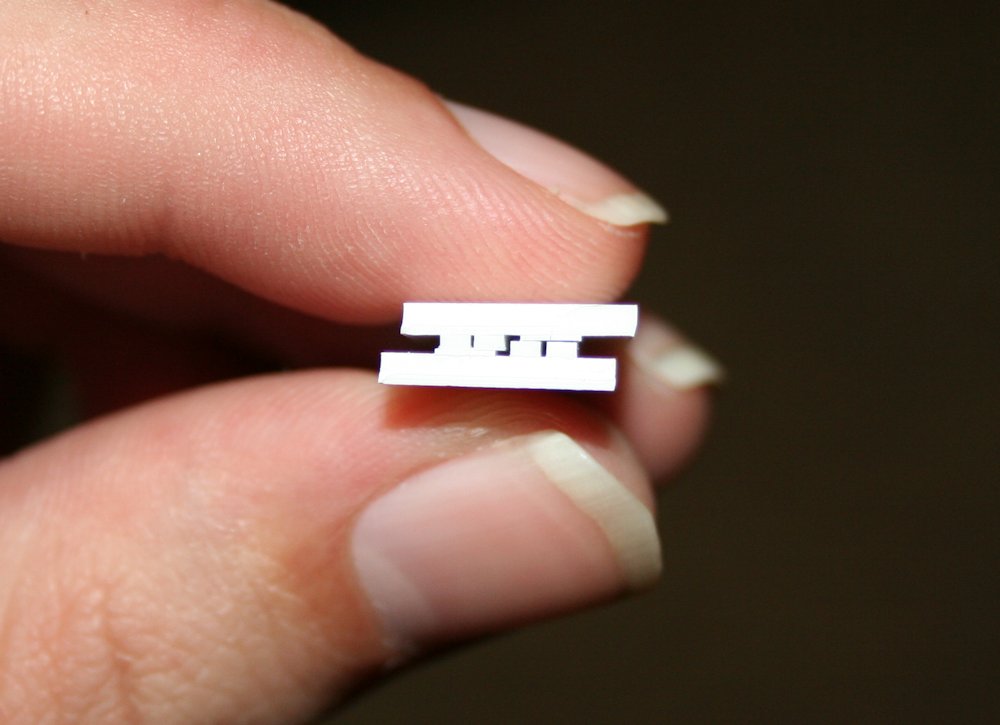
Once the cement on the jig set, I could fabricate the Z stock by inserting the strips into one end of the jig and slowly pushing them through out the other side, about a quarter to a half inch at a time and cementing them together with liquid cement applied with a very fine brush into the joint between the strips.

The result is a nice, solid structural shape that looks about as good as any solidly extruded commercial offering, and would have been extremely difficult or impossible to do free hand at such a small size.
Over the long weekend and this week I’ve had the opportunity to get back into some of my modeling. One project that I’ve re-started up is starting to fabricate the scratchbuilt end racks for a few 2300 series 40′ flatcars. I started this a long time ago, building a rough test end on an old scrap Athearn flatcar, and then managed to complete the basic outline of one (actual) end before the project wandered off onto a back burner.

Test build on a scrap Athearn flatcar from the junk pile.
The test build was done to accurate dimensions overall to test the measurements, overall look and robustness of the build, although the interior framing within the end is not to scale, just thrown in for effect and to strengthen the assembly. The simple square of butt-joined styrene strip is extremely fragile, but once assembled into a whole piece with the inner bracing and the wide walls, the whole thing is actually remarkably rigid.
The test build appearing to be rather successful, it was on to start fabricating real parts, with precision cut pieces and all the inner parts located properly.

End view of AC 2358 at Frater in 1996. Blair Smith photo.
I’m lucky to have a couple of nice dead-on end shots saved in my reference files to help scale out the ends. The dimensions listed in the equipment register give the interior height of the car (from the top of the deck boards to the top of the bulkhead) as 9’0″, and an interior width of 9’7″. Scaling from the photos, the width over the outside of the two inner square posts appears to be close to or just under 4′ across, and centred. The horizontal member is a little bit above evenly half way up the end.
The deck boards on the Athearn flat however are 9’0″ across, so fashioning the ends to add to this model to kitbash one of the ACR cars will leave the width slightly narrow, and the end rack a little bit more square than prototype. (I also measured across a Tichy kit and its width is also 9’0″.) It’s not overly noticeable, though a 6″ loss over 9’6″ is about a 5.3% difference.

One partially completed end frame, and parts for a second showing rough assembly sequence.
My outer frame is made from .030x.040″ strip for the bottom and outer side posts (as the side posts will be laminated to the thickness of the sheet used for the side of the car), and .040x.040″ for the rest of the major structural members (top and middle horizontal, and inner vertical posts). Representing the Z-shaped bar stock between the two inner square posts will be an interesting challenge yet…
To ease in the measuring and cutting, I made the top and bottom horizontal members full width, so the side and inner vertical posts are all cut to the same length and cemented between the top pieces. Then the middle horizontal pieces will be cut to fit between the spaces.
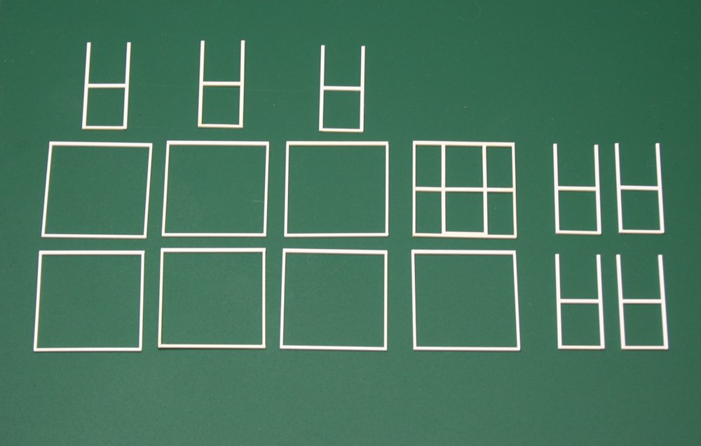
Parts and sub-assemblies for four pairs of ends.
For assembly, I glued together the outer frame first with a liquid styrene cement, using some small precision squares to keep everything aligned and square. Then the inner part of the end bracing is assembled as a unit that can be inserted into the outer frame by cutting the bottom plate from .030x.040″ strip to fit between the two posts, and the same for the horizontal part.
Once the inner frame assemblies are inserted into the outer frame and cemented together, then I’ll cut and insert the other bits of the horizontal member to finish up the basic assembly of the end frame. Then I just need to do something about the Z verticals to finish the end bracing, and move on to the sides and mounting these onto a car body.
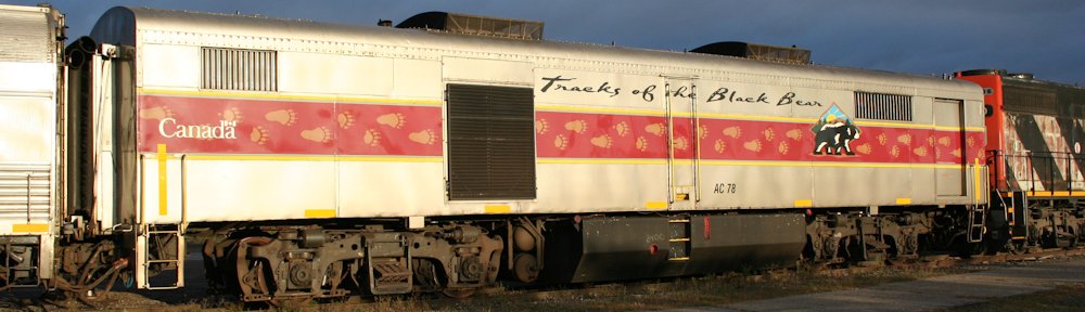
The Algoma Central rostered several distinctive designs of freight cars that didn’t exactly match anything on other railroads. One of these signature cars was a 73 car series of 40’ flatcars with a 9’ tall open framework with wraparound sides at each end of the car. These permanent end racks created a fleet of cars that could be used for pulpwood service on the ACR, delivering pulpwood from spurs and sidings along the line to the Abitibi Paper mill in Sault Ste. Marie.

AC 2358 at Frater in September 1996, loaded with fresh ties and MOW supplies. Blair Smith photo.
Pulpwood was cut in 8’ lengths and loaded widthwise in the cars, with the end racks containing the pile, and the friction of the logs’ rough surfaces holding everything else together. These cars were used extensively and primarily for this, but I’ve also seen a photo of a trio of these cars in the late 1970s loaded with wrapped lumber loads from the Newaygo Forest Products sawmill at Mead (1974-1985), and they could be used for any sort of company service load requiring an open flat car as well (being particularly well suited to loading with new ties in the same manner as pulpwood logs).
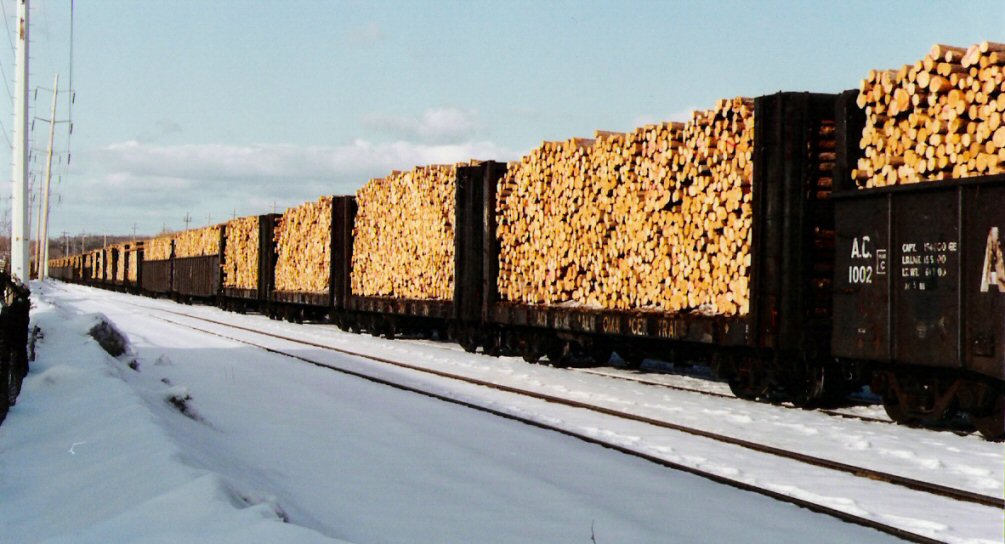
Train of pulpwood arriving at Steelton yard, early 1990s. Morgan Turney photo via James Brookman.
The exact history of these cars is unknown, but they show up on Official Railway Equipment Register (ORER) listings in two batches beginning in 1965-66. It’s likely that they are drawn from other series of 40’ flatcars with the custom end racks fabricated by the ACR’s car shops. By the early 1970s these cars no longer appear in the ORER listings, but these did remain actively in service well into the late 1980s and early 1990s (just not in interchange service and thus no longer included in the published data supplied to the ORER – a 1984 ACR freight listing reproduced in Dale Wilson’s “The Algoma Central Railway Story” indicates 69 of the 73 cars still in service), and a few examples still kicked around in company service well beyond the Wisconsin Central takeover. If any were left by the CN takeover of WC in late fall of 2001, this old equipment was likely scrapped then.
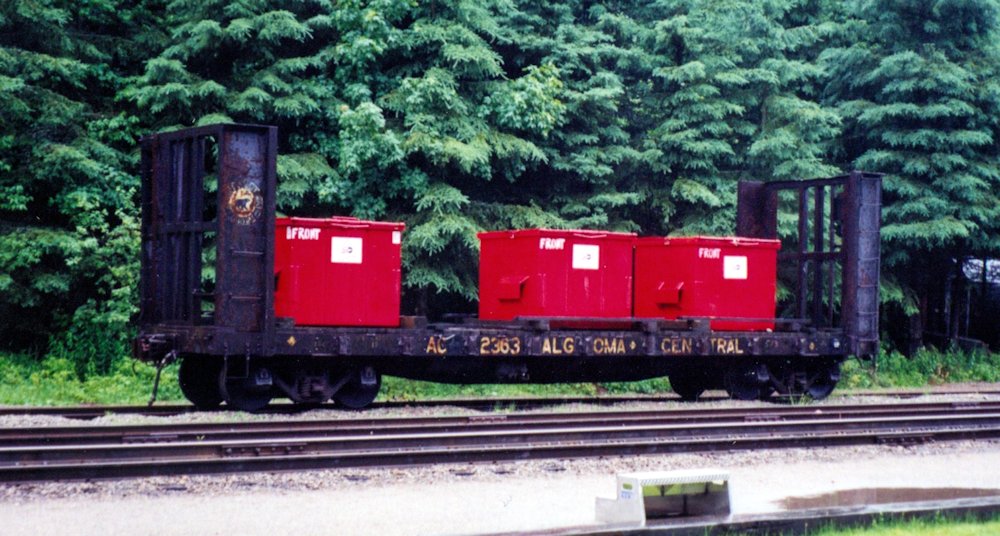
AC 2363 with trash dumpsters in the Canyon house track in 2000. Chris vanderHeide photo.
While other railways had various types of flatcars for pulpwood service with end racks or bulkheads and sometimes V-shaped decks or deck risers or dividers for loading pulpwood in 4’ long logs in two rows, the square, open framing with wraparound sides of these ACR cars makes for a distinctive looking car, particularly with the ACR bear herald emblazoned on the left hand side. Athearn even had an ancient old HO scale model from their old “Blue-Box” line of a 40’ pulpwood flatcar with superficially similar end racks, but the corners are rounded and the car has fishbelly sides and a prominent ridge in the centre of the deck. This could be used as a rough stand-in, but the divider/ridge in the middle is problematic, and the flooring of the car would have to be extensively reworked.
End view of AC 2358 at Frater, September 1996. Blair Smith photo.
To really get proper looking racks, they’d have to be scratchbuilt, either on an existing model of a 40’ flatcar with straight side sills, or a fully scratchbuilt model.