AC 300 Body Assembled

A little more work on this project tonight and the first body is assembled:

IMG_8441 IMG_8444

Starting to look like something now, although there’s still a ways to go in roof and body detailing, plus the underframe needs to be tackled. (I’ve cut the frame, but that still needs to be filed down a bit and spliced back together, then the addition of all the underbody detailing.)

I’ve already started preparing the sides for the second car now as well, I’ll be building up this pair together.

AC Baggage Cars 300-301 – Part 2: Ends and Roof

With two sides finished, I moved on to preparing the ends and cutting the roof to length.

The ends from the Train Station Products Pullman-Standard core kit just needed a minor adjustment near the bottom to handle the curved skirts at the end of the cars. The stock ends have a bit of thick bracing all the way down to the bottom, which interfered with the curved skirt on the USP side. I cut this back with my razor saw, and also shortened up these tails and filed a different curve profile into them to match my sides. A picture being worth a thousand words, the below image comparing the modified end (marked with an “A”) to the stock end probably explains it better and clearer than I can:

IMG_8427

Necessary to make the sides fit the ends properly, but pretty simple.

With the ends taken care of, it was time to tackle the roof. These baggage cars are quite a bit shorter than a full size 85′ coach, so the roof needed to be cut down to length. I ended up making a total of four cuts; with the extra piece that’s removed taken out, there were three places where the roof is spliced back together.

In a lot of the reference photos I have it’s a little difficult to make out the seams in the roof, but it appears from one or two photos that the third panel from the one end is a fair bit narrower than the others. This then is where the cuts were made to remove the extra bit of roof. I also cut the two end-most panels to narrow them down a little. A lot of careful filing to clean up the cuts and remove extra material to bring the length down to exactly the right amount for the splices, and we end up with something like this:

IMG_8410

You can see I’ve also installed the baggage doors from the kit. Like the sides, these are .020″ styrene sheet with the window openings milled out. They’re cut oversize to the opening so they can be glued to the back of the clear base. I made one modification here to the doors, trimming away the extra material below the door in order to clear the floor.

Here’s the underside of the roof, showing styrene strip used to hold the spliced roof together:

IMG_8422

You can also see in the above image that I cut away short stretches of the inner ridge on the roof in order to clear the doors on the sides.

With the ends and roof prepared, next I can assemble the car’s body!

AC Baggage Cars 300-301 from Union Station Products Kit – Part 1

With no family commitments on the Monday of the Thanksgiving weekend, I decided to make a deliberate effort to take advantage of a day off actually spent at home to do some work on various model projects. One project I’ve been working on today is a model of one of the Algoma Central’s two ex-Denver & Rio Grande Western baggage-express cars.

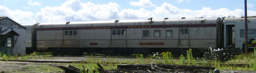
These two cars are a little unusual in that the lower portion is clad in stainless steel fluting, but the upper part of the car is smooth. Built as baggage/RPO (railway post office) cars by Pullman-Standard, these cars were originally ordered by the Chessapeak & Ohio Railroad, but ended up being delivered instead to the D&RGW in 1950. The Algoma Central acquired two of the three D&RGW cars in 1973, numbering them 209-210. In 1981 when the 200 series GP38-2s were delivered, all of the AC baggage cars were renumbered into the 300 series, and these became AC 300-301.

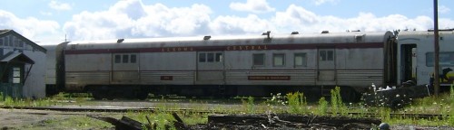
Here’s the 301 at the Steelton yard shop tracks in 2004:

SAMSUNG DIGIMAX 360

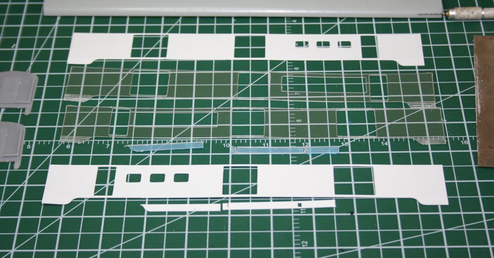
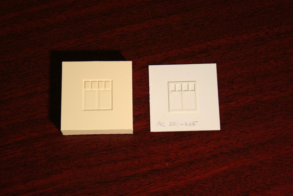
The basis for this model is a car side kit from Union Station Products. It’s one of a group of such kits I acquired back in July. (Actually I got two copies of this particular kit, so I will be able to model both car numbers 300 and 301.) The kit consists of a .020″ white styrene side and a .040″ clear plastic (acrylic?) core that are meant to be laminated together. The core has cut out sections for the windows, these to be applied later, after painting. The side kits are then meant to be used with passenger car core and detail kits from Train Station Products (which USP also resells) to provide the roof ends and underframe for the car.

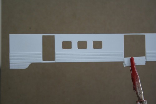
The Algoma Central removed the skirting from these cars when they acquired them, so the first stop was to perform some minor surgery on the car sides to cut away the skirting between the trucks:

IMG_8399

This was easily accomplished with a straightedge and many light passes with a sharp X-acto knife to cut away the unwanted material. Following that, it was essentially a matter of cleaning up the various pieces before assembly.

The skirting area on the clear core has a bunch of horizontally scored lines in it so that the skirts can be curved inward using pliers. (The smooth side is the outside, the cut side curves inwards.) I used a a pair of flat (not needle-nose) pliers to gently curve the remaining skirting at the car ends. Just work gently and slowly and evenly along the skirt you’re bending.

The kit instructions suggest you start with the skirting when you glue the side and core together. I started with the skirt at one corner of the car and careful to keep the whole side square and lined up, glued it to the clear core with CA glue, applied with a toothpick. After holding that in place and allowing it to set for a few moments, I proceeded out from that corner along the side of the car, applying glue to a section up to a door opening, and laminating that portion of the side. I did not go ahead and glue the skirt at the other end right away – you want to start at one end and work your way down; if you’re off by even a fraction of a millimeter you can end up with a major ripple in the side.

Once the side and core were laminated together, I spent some time going over the outer edges and also the edges of the door frames with a small flat file to clean up all the edges and remove burrs from the manufacturing process. (The sides and cores are CNC milled.)

For their fluted side cars, Union Station provides a separate strip of fluting that is laminated onto the surface of the car side. This was easy to cut to length with my Chopper and apply to the side. I attached these using Testor’s liquid cement. I applied a small amount to the back of the fluting strip to tack it in place, and once properly aligned, applied cement sparingly around the edges of the strip with a very fine point brush. This wicks into the joint and makes a very clean and permanent joint.

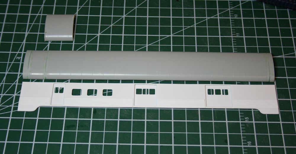
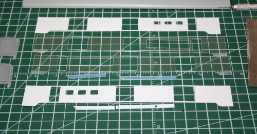
Here’s how the one side looks so far:

IMG_8403

Just need to finish the other side (actually x3 because I’m doing two of this car) and then work on the roof and underframe, which require a certain amount of cutting and splicing because the baggage cars are shorter than a typical 85′ coach which the core kits are designed for.

ex-Troop Sleeper Baggage Cars – Part 3: Plugging windows

The next step with these cars involves plating over the carbody vents and the unwanted windows. The upper vents were all plated over on these cars, but the windows varied from car to car, and were done later. Up until the late 1960s and probably into the early 1970s, the cars all would have had their original windows still. In the 1970s however, some of the cars started to have windows blanked out and plated over when they received a full shopping.

The car I’m currently working on represents AC 306 (ex-AC 205, ex-US Army 7883). Photos I’ve collected from various sources online show that on one side of the car, 3 windows (2 to the right and 1 to the left of the baggage door) were plated over, while on the opposite side, only one window to the right of the door was plated.

Note that the windows I’m referring to here are all in the first double pair of windows; the original troop sleepers have a single window on either side of the original entry door, but both of these windows and the original man door are overlapping with the space where the baggage car door will go. Those windows will need to be completely gone, not just plated over with the frame still in place. That’s a little bit more involved, so I’m leaving that until later.

I plated the required windows quite simply by cutting rectangles of .010″ styrene sheet to fit the window openings. (Actually I cut this just slightly oversize and then carefully file down the edges so that it fits in perfectly.) When you look at the windows on the model, you can see the riveted frame around the window, and then an inset window sash, which on the rear car would have been the moveable part of the window. To plate over the window, I just cut the plate to fit just inside the outer frame, and lay down on top of the recessed sash. The .010″ thickness of the styrene sheet set on top of the recessed sash perfectly represents the plated over opening.

IMG_7186

Car with upper vents and two windows at left plated over. The two windows at right will remain open and receive the original kit window glass pieces when the car is fully completed.

Similarly the vents along the top of the car body were also plugged with .010″ material but in this case their narrow width meant a 010″x.080″ strip cut to length will fit perfectly in the vent opening. Again the recessed depth is such that a .010″ strip is almost perfectly flush.

That takes care of the easy part of the car side modifications; cutting out the door, removing the single windows and smoothing everything up again will be considerably more invasive surgery.

ex-Troop Sleeper Baggage Cars – Part 2: Doors

The doors for these cars was an interesting scratchbuild project. It’s been a while since I worked out the measurements, but I was able to come up with something that looks pretty good. Here’s my drawing from my notes:

baggagedoor

Measured construction drawing of the baggage car door.

The scratchbuilt door master consists of a .020″ styrene door blank with the trimming made from scale 1″x6″ strip (except for the centre vertical that divides the lower part of the door into 2 panels with is a little wider – 1″x8″. Working carefully and measuring with my dial calipers, the trim was fixed by applying liquid styrene cement with a fine brush. My favourite here is the Testors liquid plastic cement. I highly recommend against Plastruct’s Plastic Weld in this application as I’ve found it to leave a nasty surface residue when used on styrene.

To get a nice clean upper window, I applied the trimming to the door blank before cutting out the opening. I don’t remember doing the cutting anymore, but the best approach would be to drill out the corners and then play “connect-the-dots” to cut out the rough opening. What I definitely do remember is carefully opening up the window opening with a series of fine needle files, filing the opening even with the 1×6 trim strips.

Since I knew I wanted to probably make more than one of these cars, I planned on making one door master which I could then make molds from to cast several copies in resin. The door blank was therefore cemented to a piece of .060″ styrene backing.

The window mullins were added after the door was cemented to the backing plate. This ensured that they were nice and flush. The mullins are .030x.040″ strips, laying on their wide side to match the ~.030 thickness of the .020″ door + 1×6 (.011″x.066″) trimming. These should be evenly spaced. (I didn’t keep notes for this spacing, but measuring the door master shows each window pane to be an average of .145″ wide (within a variance of .005″, well within a margin of error and not detectable by the eye).

IMG_1015

Finished door master.

Following the completion of the master, I was able to create the rubber mold from the master and use it to cast several copies of the door. I now have more than enough doors to do several cars.

IMG_1249

Rubber mold and scratchbuilt door master.