ACR Standard Speeder/Tool Shed

Today I took advantage of a nice Saturday to myself with nothing planned an unattractive weather outside to delve back into some modelling projects, and start a new one, because, why not? (Who says you can have too many projects at once?)

ACR From Blair 043

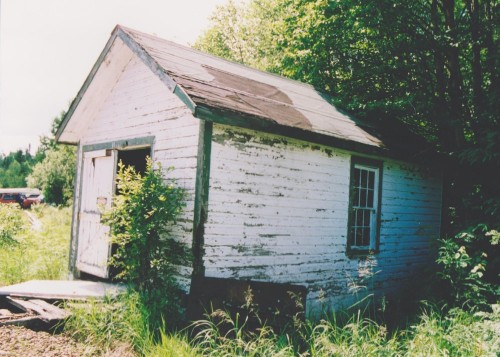
Abandoned speeder/tool shed at Frater, mid 1990s. Blair Smith photo.

This afternoon I was able to start into a project to put together a trio of standard track speeder/tool sheds for my eventual ACR layout. These are small, simple buildings, so an attractive weekend project. (Ok, so finishing these will spread over a few more weekends…) Like on most other railways, these sheds were for storing a section gang’s track maintenance tools and inspection track speeder. The wide door on the front of the shed was large enough for the speeder to enter, and the shed would be located perpendicular to the tracks with a pair of rails in front (which sometimes could even be just wooden beams) for the speeder to be rolled out to the track.

standard speeder shed nick acciavatti

Abandoned speeder/tool shed at Batchewana? August 2014. Nick Acciavatti photo.

Like most other railways, the Algoma Central had a standard design for their speeder/tool sheds; and identical structures could be seen all along the line. Surviving examples have been noted at Batchewana and Perry, and possibly still other locations. The shed at Frater pictured above is long gone.

These three models will (hopefully) eventually find their way to modelled representations of Franz and Mosher, and possibly Perry for the third one, if I ever have room to include a siding south of Hawk Junction.
IMG_0196

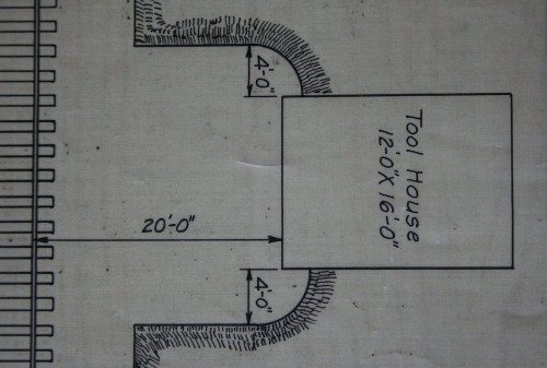
Detail from AC&HB Ry. drawing C-8-31, Standard Grass Line and Track Signs, August 19, 1946. Sault Ste. Marie Public Library Archives collection.

This excerpt from an old railway drawing in the Sault Public Library Archives gives a indication of the footprint and general relation of the tool shed to the tracks. Other dimensions were approximated from photos and I was able to work out a scale drawing and lay out the pieces on a sheet of Evergreen styrene siding. Note that the location of the window in the side of the structure is not centred. The rear and opposite side are blank walls with no windows.
IMG_1545

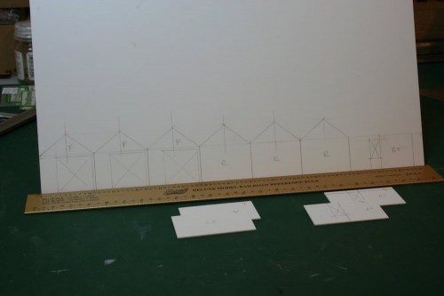
Fronts and rears for 3 speeder sheds laid out on plastic siding. Since the outlines are drawn on the *back* of the sheet, with the siding texture on the opposite side, everything is drawn as a mirror image.

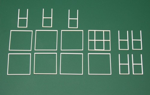
At this point so far, the parts have been cut apart and the door openings cut out. The window openings still need to be opened up on all of the side walls, and then I can start assembling things and working on the main front doors.

AC 2300 Series Flatcar Bodies and Assembly

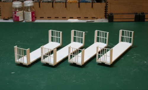
Over the past week or so I’ve been continuing to work away at my flatcar project, and I’ve built basic bodies for the four cars and completed the assembly of the ends, and now I have four assembled flatcars that are starting to look like an impression of the real thing.

IMG_1527

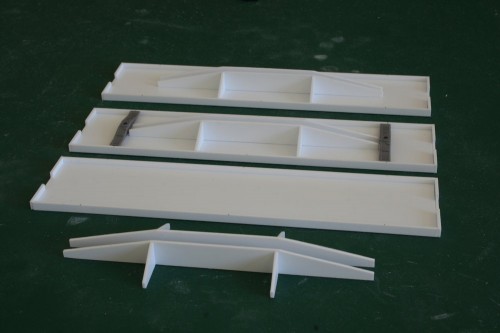
The bodies are scratch-built from .040″ thick sheet and strip. You can see in the photo below the various parts ready for assembly: the simple flat body, a basic fishbelly underframe, and the truck bolsters are Tichy parts. The side and end sills are .040″x.125″ strip, while everything else is cut from .040″ thick sheet material.

Some weight will still need to be added to the cars along with some basic underframe detailing.

IMG_1440

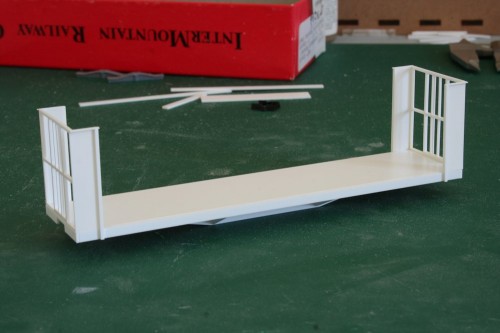
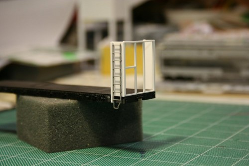
With four bodies built, the ends could be assembled and attached to the cars. With the framing for the ends previously completed, the side wings were added using .010″ thick sheet material with an .040″x.040″ reinforcing post and a .010″x.040″ top flange across the top of the side to finish everything off.

IMG_1450

Above you can see the end details on a single car; each of the four are identical.

With the basic assembly complete, these models are really starting to look like something, but there’s still a lot of work to do with the fine detailing of the car. The car still needs ladders and grab irons, brake wheel and associated end details, basic underframe brake system details, side stake pockets and decking, not to mention trucks and couplers or paint and lettering.

Scratchbuilt Ends for 2301-2373 Series Flatcar – Part 2

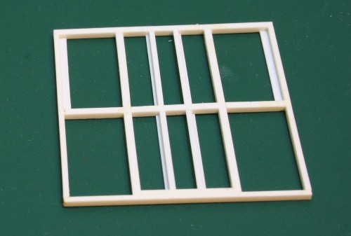
This week I managed to take the next step forward on the ends for my (current) quartet of 40′ end-rack pulpwood flatcars, finishing up the major framing on the end of the rack.

IMG_1435

Note that the inner-most vertical members on the prototype are Z angle, not square tube or bar stock like the rest of the frame. Unfortunately I couldn’t find any commercially available Z strip in the .040″ thickness I needed to match the rest of the framing; Plastruct makes some down to 1/16″ but that’s still far too large by at least 50%.

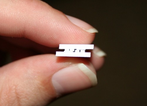
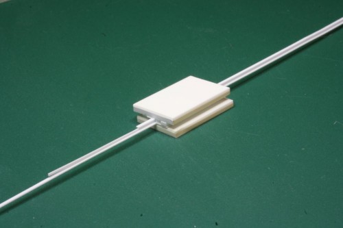
What to do when you can’t get the angle stock you need? Well, simply fabricate your own out of plain strip. To make the fabricating process easier, cleaner and more precise, I built a jig using a couple sizes of styrene strip sandwiched between a bit of scrap styrene for a top & bottom plate, with a space in the middle to feed through a pair of .010x.030″ strips (top and bottom flange) and a .010x.020″ (middle web) strip through the jig.

IMG_1427

Once the cement on the jig set, I could fabricate the Z stock by inserting the strips into one end of the jig and slowly pushing them through out the other side, about a quarter to a half inch at a time and cementing them together with liquid cement applied with a very fine brush into the joint between the strips.

IMG_1417

The result is a nice, solid structural shape that looks about as good as any solidly extruded commercial offering, and would have been extremely difficult or impossible to do free hand at such a small size.

Scratchbuilt Ends for 2301-2373 Series Flatcar – Part 1

Over the long weekend and this week I’ve had the opportunity to get back into some of my modeling. One project that I’ve re-started up is starting to fabricate the scratchbuilt end racks for a few 2300 series 40′ flatcars. I started this a long time ago, building a rough test end on an old scrap Athearn flatcar, and then managed to complete the basic outline of one (actual) end before the project wandered off onto a back burner.

IMG_7417

Test build on a scrap Athearn flatcar from the junk pile.

The test build was done to accurate dimensions overall to test the measurements, overall look and robustness of the build, although the interior framing within the end is not to scale, just thrown in for effect and to strengthen the assembly. The simple square of butt-joined styrene strip is extremely fragile, but once assembled into a whole piece with the inner bracing and the wide walls, the whole thing is actually remarkably rigid.

The test build appearing to be rather successful, it was on to start fabricating real parts, with precision cut pieces and all the inner parts located properly.

ac2358_2

End view of AC 2358 at Frater in 1996. Blair Smith photo.

I’m lucky to have a couple of nice dead-on end shots saved in my reference files to help scale out the ends. The dimensions listed in the equipment register give the interior height of the car (from the top of the deck boards to the top of the bulkhead) as 9’0″, and an interior width of 9’7″. Scaling from the photos, the width over the outside of the two inner square posts appears to be close to or just under 4′ across, and centred. The horizontal member is a little bit above evenly half way up the end.

The deck boards on the Athearn flat however are 9’0″ across, so fashioning the ends to add to this model to kitbash one of the ACR cars will leave the width slightly narrow, and the end rack a little bit more square than prototype. (I also measured across a Tichy kit and its width is also 9’0″.) It’s not overly noticeable, though a 6″ loss over 9’6″ is about a 5.3% difference.

IMG_7418

One partially completed end frame, and parts for a second showing rough assembly sequence.

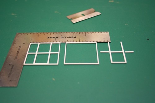
My outer frame is made from .030x.040″ strip for the bottom and outer side posts (as the side posts will be laminated to the thickness of the sheet used for the side of the car), and .040x.040″ for the rest of the major structural members (top and middle horizontal, and inner vertical posts). Representing the Z-shaped bar stock between the two inner square posts will be an interesting challenge yet…

To ease in the measuring and cutting, I made the top and bottom horizontal members full width, so the side and inner vertical posts are all cut to the same length and cemented between the top pieces. Then the middle horizontal pieces will be cut to fit between the spaces.

IMG_1097

Parts and sub-assemblies for four pairs of ends.

For assembly, I glued together the outer frame first with a liquid styrene cement, using some small precision squares to keep everything aligned and square. Then the inner part of the end bracing is assembled as a unit that can be inserted into the outer frame by cutting the bottom plate from .030x.040″ strip to fit between the two posts, and the same for the horizontal part.

Once the inner frame assemblies are inserted into the outer frame and cemented together, then I’ll cut and insert the other bits of the horizontal member to finish up the basic assembly of the end frame. Then I just need to do something about the Z verticals to finish the end bracing, and move on to the sides and mounting these onto a car body.

Scratchbuilt Boxcar Tack Boards

I spent some time this nice Sunday afternoon trying to catch up on some minor projects that have been languishing in a state of near-completion, or nearly-ready-for-the-paint-shop.

One of these projects was a pair of 50′ boxcars from Intermountain’s 50′ PS-1 boxcar kit. The one thing I didn’t really like about this otherwise excellent kit was the tackboards for the doors. (For the uninitiated, these are wooden boards mounted on or near the doors and the ends of the cars to which hazardous materials placards, or unloading or routing instruction cards could be stapled.) These tackboards generally consist of several wooden boards in a metal frame, and are usually mounted on the door of the car (for sliding door cars) or sometimes just beside the door on plug door cars.

The Intermountain kit part for the tack board has a really wide gap between the boards, which just doesn’t look right to me, so this project has been waiting on the sidelines for me to make new ones. Well, today finally I did.

This is a simple project; the tackboards themselves are 3 strips of HO scale 2″x6″ styrene cemented side by side, with the frame represented by a piece of 2×3 at each end. The 2×3 is cemented to the main 2×6 pieces such that it stands on edge, to give a little relief to the frame.

Here’s my scratchbuilt tack boards (enough for 2 cars) compared to the original Intermountain kit parts:

IMG_8755

I simply find the dividing lines on the Intermountain part way too coarse. Which is odd, because I was perfectly happy with the tack board parts on several Intermountain 40′ kits I have, and you’d expect them to be similar within the product line.

The smaller tack boards were similarly done, with the centre board made from a single piece of 2×6.


I also got a couple of 40′ boxcar kits just about ready for the paint shop, hopefully I’ll have a chance to do some spraying tomorrow evening.