AC 3100 series wood boxcars from Accurail’s 40′ wood boxcar kit

This weekend I got back to working on a couple of assorted modeling projects that I’ve had on the workbench for a while. One of these is this trio of 40′ wood boxcars.

These models represent cars from a 100-car batch built in late 1927 numbered AC 3101-3200; by the late 1970s any of these cars still running would have been restricted to maintenance service; in 1970s-1980s freight car lists in the Official Railway Equipment Register the Algoma Central lists no boxcars in interchange service. My three cars will therefore likely spend the majority of their life parked in a side track with other maintenance equipment at Hawk Junction yard as material storage cars, or moving occasional OCS (“On Company Service”, i.e. non-revenue) cargos. Here’s a good prototype photo from Ted Ellis’s Algoma Central site of one of these cars in a work train at Frater (mile 102) in 1977:

http://algomacentral.railfan.net/images/AlgoCenRy/AC_3195_Frater_6-12-1977.jpg

These three cars were modelled using Accurail’s 40′ wood boxcar kit with wooden doors and ends. This kit is a pretty close match to the AC cars; they might not be 100% dead-on – I note some minor differences in the horizontal metal straping at the top of the vertical end braces, and the doors stops are located differently, but the side bracing looks pretty much the same – it’s close enough for me.

I chose not to do a lot of fine detailing on these cars; while Accurail’s details (i.e. grab irons and ladders) are molded onto the car body and not separately applied freestanding pieces, Accurail’s tooling is fairly well rendered, and on the wood car it’s not really bothering me that much. If it was a steel car, I’d probably upgrade the detail. Might seem a bit quirky, but in this case I can accept the level of detail of the car body.

The shells were actually painted quite some time ago; these were some of the first things I painted while practicing with my new airbrush. I sprayed the shells with CN Mineral Brown from TrueLine Trains; really any shade of generic “boxcar red”/freight car brown will do here.

Lettering is from a rub-on “dry transfer” lettering set from CDS Lettering. Following photographs, I deviated from the lettering set a little. The set includes horizontal lines above above and below the reporting marks (initials) and numbers. While when new these cars would have included those in their original lettering, all photographs from later years around the 1960s-80s show these cars without these lines. As I’m modeling this later period, these lines were excluded, and the reporting marks and numberes were moved up a bit, to put the reporting marks and number around the upper grab iron on the left side.

IMG_3892

Once all three cars were lettered, I weathered them up with Bragdon weathering powders applied with a stiff brush. I kept mostly to the darker browns – burnt umber and burnt sienna – as these are wood cars I avoided the oranger rusty colours. I also used a bit of black (soot) on the roof to darken it and accent the roof ribs; and also on the sides to darken and bring out the board detail of the sides. The Accurail car has a lot of grain molded into the sides and accenting this really gives the car a more worn appearance. I also tried concentrated the darked colours around the door opening and the end of the door track where rain would tend to wash off the car roof to try to make these areas a bit darker and more weather-worn. This wasn’t precision detailing, and it spreads out a lot by working it with the brush, and the effects of the powders are actually very subtle, but I think it did generally work to darken the general area just a bit. It’s not necessarily really consciously noticeable that those areas specifically have been darkened, but it brings out the details and the wood grain of the sides, and darkens and varies the colour of the car a bit. And on a couple of the cars even from a distance (maybe even more from a distance) the door and right side of the car is slightly darker in colour than the left side where the majority of the lettering is.

I then gave the three cars a quick spray of Dullcote last night to seal the lettering and weathering. Here’s a pair of the cars mounted back on their underframes and posed on my switching layout with one of my Overland cabooses:

IMG_7291

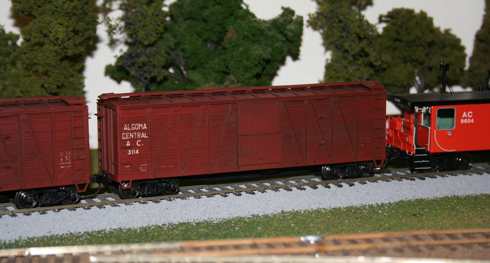
There’s a few details to be done yet, and the underframe needs some minor detailing and then the frame, trucks and wheels all need to be painted/weathered. The completed car will probably get some additional road weathering along the bottom at that time yet as well, but that’s another day.

AC 8201-8500 series hoppers – Part 3: End platform grating

Here’s a good view of what the end of one of these cars looks like:

http://rrpicturearchives.net/showPicture.aspx?id=1251473

While the stock Walthers model basically just has some generic raised-tread pattern on the end, you can see that the pattern of walkway grating is quite distinctive, and I wanted to capture this.

The following wreck photo also highlights quite clearly how the grating is open, and would be see-through:

http://algomacentral.railfan.net/images/AlgoCenRy/AC_Mile_5_wrk-5_5-14-1980.jpg

If I were only doing one of these cars, I might consider completely cutting away the end platforms and rebuilding them from scratch to have the open grating, however for the sheer volume of these cars that I need, I’ve decided this would be far too much time and effort to be worth it.

I do however wish to at least replicate the tread pattern, which is a big difference from the model. To this end, after disassembling the cars and removing the handrail pieces, I filed the top surface of the end platforms smooth to remove the existing tread texture.

IMG_6616

End platform filed smooth.

I cut the new walkways out of etched brass walkway/grating material. The walkways are a rectangular “Apex” tread pattern. I’ve been using etched brass material from Details Associates. I just used a regular pair of scissors to cut the thin brass sheet.

There’s two parts to the walkway tread on these cars. There’s the grating on the open area of the platform, and an extra bit of grating leading to the end ladder. The platform grating is cut out of the etched material in a rectangle 2.5 by 10.75 scale feet in size. The cut piece should all be whole rectangles, with the “grain” following the width of the car.

The walkway to the end ladder grabs is oriented perpendicular to the platform grating. With the sizing of the rectangles in the Details Associates etching, I cut a strip from the etched sheet 3 rectangles wide; this is perfectly the size to fit between the platform grating and the car body. I then cut these into approx. 1.75 scale foot pieces.

With all the piece cut, I attached them to the prepared underframe pieces using CA adhesive. Very carefully, trying not to glue my fingers to themselves or the car, I used a toothpick to spread the CA across the bottom surface of the grating, and then applied the grating material to the car. For the smaller pieces I used a pair of curved tweezers to move them into position.

IMG_7289

Several finished platforms, with one just filed smooth in the middle.

IMG_7290

Completed walkway/platform grating with the underframe and body fitted together, showing how the walkway accesses the end ladder.

This is the current point I’m at with these cars (well, the 9 I’m [semi-]actively working on). 5 cars now have the grating complete (I just finished a few of them up tonight) and another 4 have the platforms filed and prepared (and actually have for quite some time now).

After I finish this current batch of cars, (I’m hoping to try to bring these 9 all the way through to completion now) I’ve got another 50 or so of these Walthers cars waiting for the same treatment at some point!

ex-Troop Sleeper Baggage Cars – Part 3: Plugging windows

The next step with these cars involves plating over the carbody vents and the unwanted windows. The upper vents were all plated over on these cars, but the windows varied from car to car, and were done later. Up until the late 1960s and probably into the early 1970s, the cars all would have had their original windows still. In the 1970s however, some of the cars started to have windows blanked out and plated over when they received a full shopping.

The car I’m currently working on represents AC 306 (ex-AC 205, ex-US Army 7883). Photos I’ve collected from various sources online show that on one side of the car, 3 windows (2 to the right and 1 to the left of the baggage door) were plated over, while on the opposite side, only one window to the right of the door was plated.

Note that the windows I’m referring to here are all in the first double pair of windows; the original troop sleepers have a single window on either side of the original entry door, but both of these windows and the original man door are overlapping with the space where the baggage car door will go. Those windows will need to be completely gone, not just plated over with the frame still in place. That’s a little bit more involved, so I’m leaving that until later.

I plated the required windows quite simply by cutting rectangles of .010″ styrene sheet to fit the window openings. (Actually I cut this just slightly oversize and then carefully file down the edges so that it fits in perfectly.) When you look at the windows on the model, you can see the riveted frame around the window, and then an inset window sash, which on the rear car would have been the moveable part of the window. To plate over the window, I just cut the plate to fit just inside the outer frame, and lay down on top of the recessed sash. The .010″ thickness of the styrene sheet set on top of the recessed sash perfectly represents the plated over opening.

IMG_7186

Car with upper vents and two windows at left plated over. The two windows at right will remain open and receive the original kit window glass pieces when the car is fully completed.

Similarly the vents along the top of the car body were also plugged with .010″ material but in this case their narrow width meant a 010″x.080″ strip cut to length will fit perfectly in the vent opening. Again the recessed depth is such that a .010″ strip is almost perfectly flush.

That takes care of the easy part of the car side modifications; cutting out the door, removing the single windows and smoothing everything up again will be considerably more invasive surgery.

ex-Troop Sleeper Baggage Cars – Part 2: Doors

The doors for these cars was an interesting scratchbuild project. It’s been a while since I worked out the measurements, but I was able to come up with something that looks pretty good. Here’s my drawing from my notes:

baggagedoor

Measured construction drawing of the baggage car door.

The scratchbuilt door master consists of a .020″ styrene door blank with the trimming made from scale 1″x6″ strip (except for the centre vertical that divides the lower part of the door into 2 panels with is a little wider – 1″x8″. Working carefully and measuring with my dial calipers, the trim was fixed by applying liquid styrene cement with a fine brush. My favourite here is the Testors liquid plastic cement. I highly recommend against Plastruct’s Plastic Weld in this application as I’ve found it to leave a nasty surface residue when used on styrene.

To get a nice clean upper window, I applied the trimming to the door blank before cutting out the opening. I don’t remember doing the cutting anymore, but the best approach would be to drill out the corners and then play “connect-the-dots” to cut out the rough opening. What I definitely do remember is carefully opening up the window opening with a series of fine needle files, filing the opening even with the 1×6 trim strips.

Since I knew I wanted to probably make more than one of these cars, I planned on making one door master which I could then make molds from to cast several copies in resin. The door blank was therefore cemented to a piece of .060″ styrene backing.

The window mullins were added after the door was cemented to the backing plate. This ensured that they were nice and flush. The mullins are .030x.040″ strips, laying on their wide side to match the ~.030 thickness of the .020″ door + 1×6 (.011″x.066″) trimming. These should be evenly spaced. (I didn’t keep notes for this spacing, but measuring the door master shows each window pane to be an average of .145″ wide (within a variance of .005″, well within a margin of error and not detectable by the eye).

IMG_1015

Finished door master.

Following the completion of the master, I was able to create the rubber mold from the master and use it to cast several copies of the door. I now have more than enough doors to do several cars.

IMG_1249

Rubber mold and scratchbuilt door master.

AC 8201-8500 series hoppers – Part 2: Interior and Top Chord

So in my previous post, I introduced this project and the prototype for these cars, 300 cars built by NSC to an Ortner design in 1974-75. Walthers makes an HO model of the Ortner design, which makes a convenient start to this project. Of course there are some details, both major and minor, that differ between the Walthers model and the AC prototype cars.

IMG_6612

Stock Walthers model without the hokey included aggregate load.

The biggest change that needs to happen is that the AC cars have tubular V-bracing between the bays, not the solid bulkheads that the model has. This takes a little bit of work, but is not difficult, and you’ll agree this makes a huge difference in appearance.

If you only want to do minimum changes or detailing to turn the Walthers car into a reasonably accurate AC car, this is the change to make. Also, since the insides of the cars were unpainted steel, this change can be done on a factory painted car while completely preserving the factory lettering, as the inside of the car should be masked and repainted a rusty colour.

The first step is the easiest, just take out the removeable bulkhead pieces and throw them away. (Or, toss them in the scrapbox. A good model railroader is a pack rat; you never know when that oddball useless leftover part now can be repurposed for something completely unintended later. Or at the very least chopped up into smaller pieces or used as part of a steel scrap load or junkyard scene.) Then I fill the holes left behind with modeling putty. Most of the cars I’ve been working on so far I’ve filled the holes using either Tamiya or Squadron putties. Other modelers also recommend Bondo putty from the automotive department, and I’ll probably try that in the future. Canadian Tire is a lot more convenient than the local hobby shops that are an hour+ away.

SAMSUNG DIGIMAX 360

Several cars in progress.

Once the body putty has had a day to cure, I file it down even with the inside surface of the sides and sand it smooth with progressively finer sandpapers. Once again the automotive aisle at Canadian Tire is rather handy here as a source for 1000+ grit finishing/polishing sandpapers to get a nice smooth interior side.

Smoothing out the bottom of the bays is a bit more tricky with the angled geometries, so I just did the best I could. A sanding stick from the hobby shop gets a good start here.

sandstick1

I used a sanding stick like this one on the inside of the bays.

Now, before I move on to installing the interior bracing, I finish cleaning up the top of the car body. (Or this part can really be done first.) The AC cars have an overhanging lip over the top of the car end that the model doesn’t have. I modeled this simply using an HO scale 2″x6″ styrene strip across the top of the end. First, however, two little angle pieces need to be carved off the top of the corners on the model and filed flush with the top of the end, as indicated in the below photo marked with arrows:

IMG_6983

Remove corner detail on top surface at points indicated to allow 2×6 header to be installed.

Once this detail is removed and smoothed down, the end cap is installed. I simply cut a piece of styrene 2×6 to length and cement it to the top of the edge. Once the end cap has been installed and the cement has set, I file down the angled top chord on the model flush all the way around with the top of the 2×6 end cap.

IMG_6986

End cap installed. End handgrabs are partially installed on this car.

Once the sides are finished, the interior bracing can be installed.

I made the braces from .040″ brass rod/wire. The rod is cut to length (approx. 1.20″) and I file one end off at an acute angle so that it rests properly against the side. Test fit this several times before glueing in place.

I drilled a small hole right next the the centre sill of the car between the bays to accept the bottom end of the brace. Then I simply use a drop of CA glue to secure both ends of the brace.

IMG_6618

Interior bracing.