25 Hopper Interiors Completed

Slowly but surely over the last few weeks I’ve been working on completing the interior detailing on all of the Walthers hoppers I’ve stripped so far. That’s a total of 25 cars currently in progress at the same time. (This actually represents a little under half my current fleet of these cars.)

These twenty-five cars now have the interior bracing and the treatment to the top chord completed. I explain the modifications a bit more in this previous post, but the process basically involves patching the holes on the inside of the body (where the solid bulkhead part from the stock model was fitted) with body putty, adding the extended lip over the end of the car, filing the top of the sides smooth, instead of the peaked side on the model representing an angle iron for stiffening, and finally installing the new interior bracing. On the older cars I did, I fashioned the bracing from .040″ brass wire, but I’ve now taken to using 3/64″ (.047″) styrene rod from Evergreen to make these, as it’s far easier to file and work with, and the welded styrene-styrene bond is stronger and more flexible than the brittle CA bond to glue the brass to the plastic body.

IMG_8562 IMG_8563

Now i just need to get the other twenty end platforms all up to the same point…

Backdated ExactRail 65′ CP Gondola – Part 2: Corner ladders

In my previous post, I cut away and replaced the ends on an ExactRail 65′ Hawker-Siddeley CP gondola to backdate the model to an older National Steel Car version of a similar car. After a couple more evenings of work, the car now has its new corner ladders installed.

The last bit of major surgery on the car body was to carve away the top chord over the last panel on the right hand side of the car, as the NSC cars have a notch here for taller ladders. Comparing prototype photos of the NSC and H-S (which the stock model represents) versions, the NSC car has a 5-rung ladder with closer spacing compared to a 4-rung ladder on the H-S car. With the top chord cut away, the area was filed smooth and the new notched bit formed out of a scale 2″x6″ top piece and an angled bit cut and filed from a piece of 6″x6″. This little assembly was then cemented in place, and the cracks and seams filled in with Bondo body putty. (At this time the seams between the new end and the sides of the car body were also touched up with body putty.)

IMG_8495

After the putty set up overnight, everything was filed and wet-sanded smooth. Then the ladders could be installed.

The ladders are cut to length from Tichy 8-rung boxcar ladders, and the rung spacing works out perfectly. Note the sides have a 5-rung ladder, and the ends have a shorter 4-rung ladder. The rungs of the side and end ladders align which each other. Note also that on the H-S car, the ladders are mounted below the heavy top chord, but on the NSC car that the modified model is intended to represent the top rung of the ladder is in front of the shallow top chord on the end, and located within a notch in the heavy side top chord.

IMG_8494

Also unlike the later H-S car, which has ladders at every corner of the car, the opposite corners on the NSC car just have a pair of grab irons instead of full ladders. The next step will involve drilling and installed these, and a few other minor details, and then I’ll be able to tackle the underframe modifications.

Backdated ExactRail 65′ CP Gondola – Part 1

A good portion of the traffic on the Algoma Central is finished steel products, and as a 300 mile wilderness route with no industrial users of this steel, basically one hundred percent of this traffic was interchanged to other railways, particularly in Sault Ste. Marie (CP and SOO Line), Oba (CN) and to a lesser extent Franz (CP). As such, CN and CP also provided a certain amount of cars for steel loading, so open cars from these railways would also be a regular sight on Algoma Central trains.

A few years ago, ExactRail released a model in their “Signature Series” of a Canadian Pacific 65′ gondola. This car is based on a version of a car built in the early to mid 1970s by Hawker-Siddeley and Marine Industries. Many of these are still in service today, so this is an excellent choice to be a part of my Canadian Pacific fleet. To add a little variety to the several cars I’ve collected, I’ve always been intending to take at least one car and backdate it to a late 1960s National Steel Car version of the same car. The NSC version is almost identical, having the same overall dimensions, number of side ribs, tie downs, etc., but has different ends and ladder arrangements. While the later HST/MIL cars have a distinctive ribbed end, the NSC car’s end is a solid, flat panel. Also, the NSC cars were built just before the introduction of CP Rail’s new “MultiMark” paint scheme, and were thus delivered in the older black paint. Interestingly, these cars were painted in simple block lettering, even though the Canadian Pacific script lettering was then the current lettering scheme in use at the time.

img0132

CP 336702 at Guelph Junction, sometime in the 1990s. Jurgen Kleylein photo.

The first step was to disassemble the car and remove most of the little detail bits. Then I cut away the original end with a razor saw and cleaned things up with a file. The side extensions that cap off the horizontal end ribs were also cut back and the bottom rib, which is below the level of the interior floor on the model, was carved away and things filed smooth. Then a plate of .040″ thick styrene was installed in the opening to form the core of the new end. The surface of this plate needs to be flush with the rest of the cleaned up end for the rest of the project to work.

IMG_8483IMG_8482

With the core of the new end in place, I cut away the protruding tail ends of the top chords of the sides flush with the end plate, and started framing in the new end with a 2×6 top chord and 2×4 framing around the sides and bottom. (Actually in the photo below I goofed and used a 4×6 on the top chord, which roughly matched the thickness of the top chord on the sides, but checking the prototype photo above, you can see it’s not actually that prominent on the end and is a lot more flush, so I had to cut this away and replace it with thinner material.)

IMG_8488

The basic assembly of the end was then finished off by cutting and filing a rectangle of .010″ styrene to fit snugly inside the end framing. Ladders and other details still need to be re-added, but here you can see the assembled end compared to the original ExactRail end on the car to the left.

IMG_8493

AC 8201-8500 series hoppers – Part 3: End platform grating

Here’s a good view of what the end of one of these cars looks like:

http://rrpicturearchives.net/showPicture.aspx?id=1251473

While the stock Walthers model basically just has some generic raised-tread pattern on the end, you can see that the pattern of walkway grating is quite distinctive, and I wanted to capture this.

The following wreck photo also highlights quite clearly how the grating is open, and would be see-through:

http://algomacentral.railfan.net/images/AlgoCenRy/AC_Mile_5_wrk-5_5-14-1980.jpg

If I were only doing one of these cars, I might consider completely cutting away the end platforms and rebuilding them from scratch to have the open grating, however for the sheer volume of these cars that I need, I’ve decided this would be far too much time and effort to be worth it.

I do however wish to at least replicate the tread pattern, which is a big difference from the model. To this end, after disassembling the cars and removing the handrail pieces, I filed the top surface of the end platforms smooth to remove the existing tread texture.

IMG_6616

End platform filed smooth.

I cut the new walkways out of etched brass walkway/grating material. The walkways are a rectangular “Apex” tread pattern. I’ve been using etched brass material from Details Associates. I just used a regular pair of scissors to cut the thin brass sheet.

There’s two parts to the walkway tread on these cars. There’s the grating on the open area of the platform, and an extra bit of grating leading to the end ladder. The platform grating is cut out of the etched material in a rectangle 2.5 by 10.75 scale feet in size. The cut piece should all be whole rectangles, with the “grain” following the width of the car.

The walkway to the end ladder grabs is oriented perpendicular to the platform grating. With the sizing of the rectangles in the Details Associates etching, I cut a strip from the etched sheet 3 rectangles wide; this is perfectly the size to fit between the platform grating and the car body. I then cut these into approx. 1.75 scale foot pieces.

With all the piece cut, I attached them to the prepared underframe pieces using CA adhesive. Very carefully, trying not to glue my fingers to themselves or the car, I used a toothpick to spread the CA across the bottom surface of the grating, and then applied the grating material to the car. For the smaller pieces I used a pair of curved tweezers to move them into position.

IMG_7289

Several finished platforms, with one just filed smooth in the middle.

IMG_7290

Completed walkway/platform grating with the underframe and body fitted together, showing how the walkway accesses the end ladder.

This is the current point I’m at with these cars (well, the 9 I’m [semi-]actively working on). 5 cars now have the grating complete (I just finished a few of them up tonight) and another 4 have the platforms filed and prepared (and actually have for quite some time now).

After I finish this current batch of cars, (I’m hoping to try to bring these 9 all the way through to completion now) I’ve got another 50 or so of these Walthers cars waiting for the same treatment at some point!

AC 8201-8500 series hoppers – Part 2: Interior and Top Chord

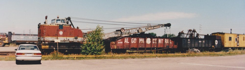
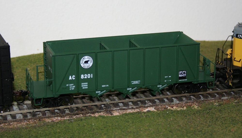
So in my previous post, I introduced this project and the prototype for these cars, 300 cars built by NSC to an Ortner design in 1974-75. Walthers makes an HO model of the Ortner design, which makes a convenient start to this project. Of course there are some details, both major and minor, that differ between the Walthers model and the AC prototype cars.

IMG_6612

Stock Walthers model without the hokey included aggregate load.

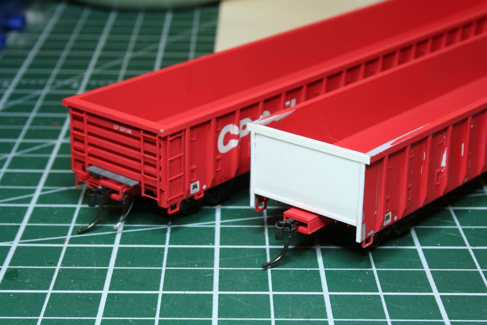
The biggest change that needs to happen is that the AC cars have tubular V-bracing between the bays, not the solid bulkheads that the model has. This takes a little bit of work, but is not difficult, and you’ll agree this makes a huge difference in appearance.

If you only want to do minimum changes or detailing to turn the Walthers car into a reasonably accurate AC car, this is the change to make. Also, since the insides of the cars were unpainted steel, this change can be done on a factory painted car while completely preserving the factory lettering, as the inside of the car should be masked and repainted a rusty colour.

The first step is the easiest, just take out the removeable bulkhead pieces and throw them away. (Or, toss them in the scrapbox. A good model railroader is a pack rat; you never know when that oddball useless leftover part now can be repurposed for something completely unintended later. Or at the very least chopped up into smaller pieces or used as part of a steel scrap load or junkyard scene.) Then I fill the holes left behind with modeling putty. Most of the cars I’ve been working on so far I’ve filled the holes using either Tamiya or Squadron putties. Other modelers also recommend Bondo putty from the automotive department, and I’ll probably try that in the future. Canadian Tire is a lot more convenient than the local hobby shops that are an hour+ away.

SAMSUNG DIGIMAX 360

Several cars in progress.

Once the body putty has had a day to cure, I file it down even with the inside surface of the sides and sand it smooth with progressively finer sandpapers. Once again the automotive aisle at Canadian Tire is rather handy here as a source for 1000+ grit finishing/polishing sandpapers to get a nice smooth interior side.

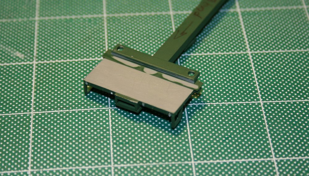
Smoothing out the bottom of the bays is a bit more tricky with the angled geometries, so I just did the best I could. A sanding stick from the hobby shop gets a good start here.

sandstick1

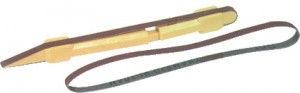
I used a sanding stick like this one on the inside of the bays.

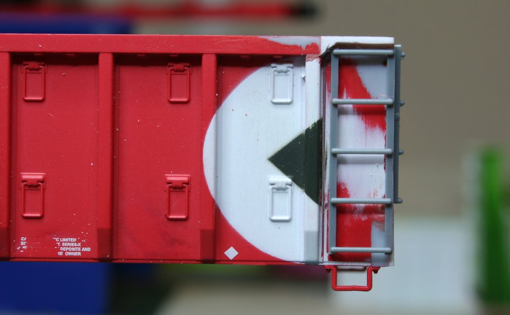
Now, before I move on to installing the interior bracing, I finish cleaning up the top of the car body. (Or this part can really be done first.) The AC cars have an overhanging lip over the top of the car end that the model doesn’t have. I modeled this simply using an HO scale 2″x6″ styrene strip across the top of the end. First, however, two little angle pieces need to be carved off the top of the corners on the model and filed flush with the top of the end, as indicated in the below photo marked with arrows:

IMG_6983

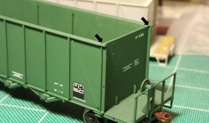
Remove corner detail on top surface at points indicated to allow 2×6 header to be installed.

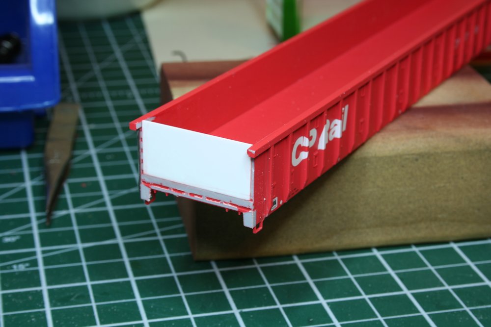
Once this detail is removed and smoothed down, the end cap is installed. I simply cut a piece of styrene 2×6 to length and cement it to the top of the edge. Once the end cap has been installed and the cement has set, I file down the angled top chord on the model flush all the way around with the top of the 2×6 end cap.

IMG_6986

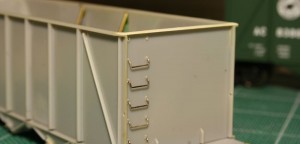
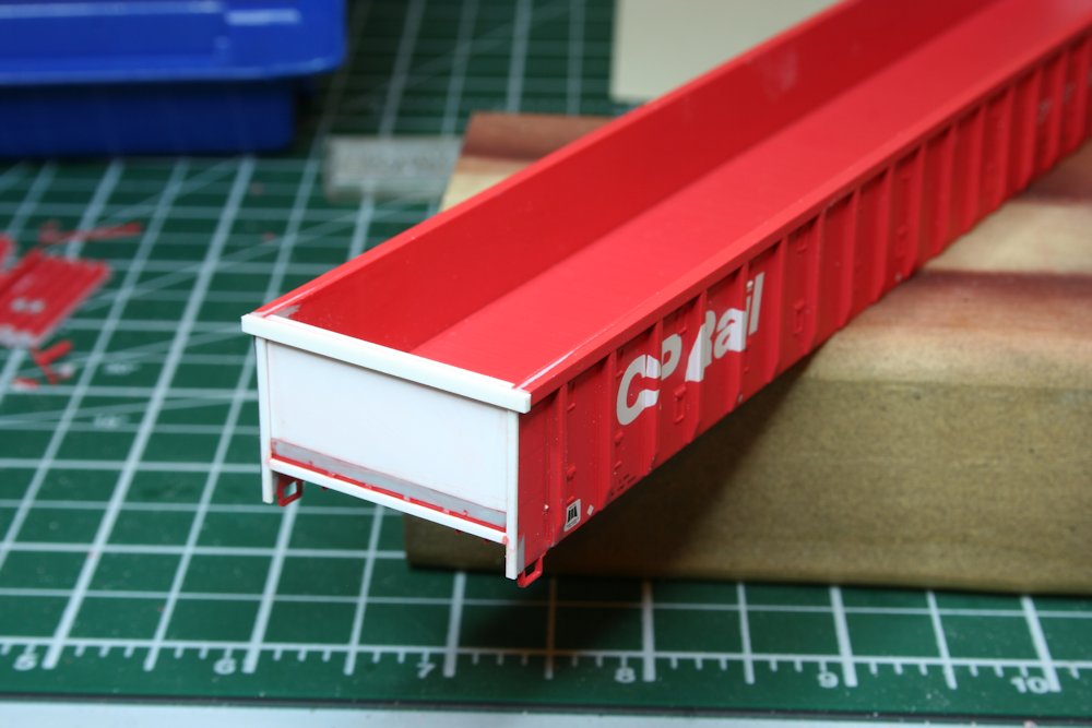
End cap installed. End handgrabs are partially installed on this car.

Once the sides are finished, the interior bracing can be installed.

I made the braces from .040″ brass rod/wire. The rod is cut to length (approx. 1.20″) and I file one end off at an acute angle so that it rests properly against the side. Test fit this several times before glueing in place.

I drilled a small hole right next the the centre sill of the car between the bays to accept the bottom end of the brace. Then I simply use a drop of CA glue to secure both ends of the brace.
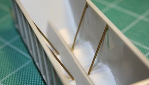
IMG_6618

Interior bracing.