CP 305513 Bulkhead Flatcar Kitbash

This week I had a chance to spend some time bringing an older project back onto the work bench – a kitbash of a somewhat lesser-known obscure Canadian Pacific bulkhead flatcar design.

cp305513_3

This example was photographed by fellow WRMRC member Jurgen Kleylein in work train service in or near Sudbury in the late 1990s. It’s actually an interesting example of a prototype kitbash, as it is one of a 60-car series rebuilt with bulkhead ends from standard flatcars. Naturally given such a unique look, I had to plan to do one myself.

IMG_1731

I started with an old Life-Like Proto2000 53′ flatcar kit, for which I made a new deck from Evergreen scribed sheet, and scratch-built the bulkheads from styrene sheet and strip. The main body construction was actually done some time ago, but the car has been sitting in storage since then waiting for further detailing. So this week I decided to pull this out and complete that job, adding ladders, grab irons and brake hardware.

IMG_1726

This close-up of the end shows most of the major details. The brake hardware is from a Tichy brake details set, and the ladders are also Tichy.

Note the side ladders are mounted with small bits of styrene strip to raise them away from the sides of the wrap-around bulked, as the ladder has pass over the angled edge of the bulkhead. Likewise, as the brake hardware has to be mounted over the ribs on the ends, the brake housing and platform supports are also attached to pieces of styrene strip for mounting.

Lastly, with the final details installed over the last few days, this evening I cleaned and prepared the car for painting, and fired up the airbrush to give it an initial coat of light grey undercoat/primer.

Next up, some CP Action Red.

CP 48551 Completed

Today I received the last needed decals for the excess height markings for this car in the mail and finished off the last little details on this car. Just in time to deliver it to this weekend’s operating session at the model train club.

IMG_1176

This was kitbashed from an Intermountain 40′ boxcar, with the body cut and spliced to extend the height. One of the greatest advantages of the Intermountain kit for this job is that the roof, ends, body and doors are all separate pieces, and the ends, doors and roof on the prototype car all have their splices and extra material in different spots.

IMG_1180

The lettering and various markings was cobbled together from a mix of Microscale, Highball Graphics and CDS sets. Photos of prototype cars show quite a variety in the exact positioning of different pieces of the lettering, no two seems quite the same.

cp41024

This model is based on prototype photos of about 4 different cars in the CP 41000-41029 series (the above example courtesy Jurgen Kleylein), which was rebuilt in 1980, but I numbered it after a car in the small 3-car series 48550-48552 which existed in the mid 1970s and has the same reported dimensions and features. Unfortunately, I’ve not found any photos of any of these cars, so I’ve exercised a little modeller’s license and an educated guess that their appearance would be the same or at least similar.

IMG_8467

The extra-tall squished multimark was custom masked and painted to fit.

CP 31236

Taking advantage of the long weekend at home to work on a few projects on the bench.

First up is completing some basic weathering on this Canadian Pacific woodchip boxcar:

IMG_1093

This car was built from an Intermountain 40′ PS-1 boxcar kit, with scratchbuilt chip doors, custom painted and lettered mostly with CDS transfers, with some Microscale sets to fill in some of the detail lettering and the U-1 inspection dot. Weathering was done with artist’s pan pastels.

This car will probably wind up in service over at the club layout; woodchips were shipped from Dubreuilville on the ACR to Terrace Bay on the Canadian Pacific using cars supplied by CP, but the best information I have suggests that this particular service was mainly in 52′-60′ gondolas, not boxcars, and it’ll be a few years yet before I have anything running, so this can join another 5 or 6 similar cars in a chip service pool on the club layout.

CP Woodchip Boxcar – 6′ Chip Doors

In the late 1970s and early 1980s, Canadian Pacific converted several hundred old 40′ boxcars into woodchip gondolas via the simple expedient of cutting away the roofs of the cars. While there were some variations (including some older International of Maine conversions that had the height of the sides extended and doors widened to 8′) the standard conversion in the 1980s was a simple 40′ boxcar with standard 6′ door with the roof cut away and the original sliding doors replaced with a two-piece hinged wooden door.

Source cars for these conversions were drawn from various different original series, and there’s a lot of variation in these converted cars.

The mill at Dubreuilville shipped out large amounts of woodchips in cars supplied by Canadian Pacific to pulp mills along the Lake Superior north shore at Marathon or Terrace Bay. So I can use a collection of CP woodchip service cars for this traffic. The ACR would have handled these cars just the short distance between Dubreuilville and Franz. Extra empties were apparently typically stored in the siding at Wanda, between Dubreuilville and Franz.

IMG_8765

This car is a Intermountain kit for a Pullman-Standard “PS-1” 40′ boxcar. (“PS-1” was actually Pullman-Standard’s catalog designation for ANY boxcar they produced, although model railroaders have (somewhat erroneously) come to associate the term with just Pullman-Standard’s earlier post-war designs.) The body details are assembled pretty much as according to the kit although the roof and doors are left out.

IMG_8768

The main visual feature of the car (apart from the missing roof) is the new chip doors, which necessitated the scratchbuilding of said doors from styrene.

The new door is a piece of .020″ styrene sheet cut to fit the door opening, trimmed with .010″x.060″ strip for the edges of the door panel. The horizontal door locking bar and the “mounting pads” under the hinges are pieces of .010″x.040″ strip. The flat parts of the door hinges are represented by pieces of .005″ styrene, basically eyeballed and cut with a razor blade, and the actual hinge parts at the edge of the door, and the vertical locking bar at the top of the door are bits of thin brass wire.

The bottom hinge plate at the foot of the door is a piece of .015″x.156″ strip with a .020″x.020″ trim piece along the top.

IMG_8769

Because the car is open, and thus has little or no way to hide any weight, I inserted a styrene false floor into the car which hides a thin layer of sheet lead flashing to give the car weight.

IMG_8771

The roofs on most of these cars were removed simply by torching out the panels in between the roof ribs (carlines). Most of these cars kept these ribs in place to hold the car together, but over time these got banged up and damaged and cars would be missing many of them. I used T-section styrene shapes to make a representation of these remaining roof ribs, leaving several out as “missing”.

This pretty much completes the major details of this particular car; next step is painting.

AC 8201-8500 Series Hoppers – Part 4: Grab Irons

Over the last few weeks I’ve been slowly working on this hopper project again, drilling out the myriad holes for the car body grab irons. This project languished for a while as I didn’t have any #80 drill bits (darn things are so easy to break!) so I had to order a few, and I’ve just been pretty busy through the last couple of months with the December holiday season and other things. However a week or two after New Year’s I got my order of fresh drill bits, and I’m trying to deliberately spend a little time at least one or two nights a week on projects. Of course the primary project I’ve started to get back into is my 25 car batch of hoppers where each step of progress takes a bit of time due to the volume of cars being worked on at the same time. And drilling out that many small holes on 25 bodies and frames has taken a few weeks to complete. So that has accounted for my dearth of recent updates. However I am trying to get some momentum going again, and hopefully get some other smaller projects finished off as well.

So, without further ado, back to the hopper project! Over the years this model has moved between different product lines at Walthers: first their standard line, then “Gold Line” with metal wheels, then “Platinum Line” which have wire grab irons factory installed. (And I think with the latest release(s) the model has been shifted again into the “Proto” series (the old Proto 2000 line inherited from Life-Like), although I really don’t think this model belongs in that category.) Earlier releases before the models were upgraded to the “Platinum” line did not have grab irons installed. I’ve been collecting these cars for quite a while now (and grabbing cheaper pre-“Platinum” cars at shows and on eBay to build up the fleet) so I have a lot of both.

Body Grabs

A bit of comparison of prototype photos to the model reveals a couple of interesting minor details.

First, the prototype AC cars have an additional grab mounted off the top cap on the end (which of course the model does not have, and which I discussed in an earlier post).

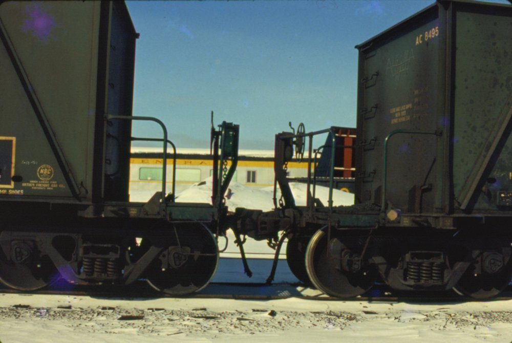
Secondly, when comparing end photos of the first batch of cars (AC 8201-8400) to the second batch (AC 8401-8500), notice that the first series has one extra grab iron compared to the later series:

ACR From Blair 012

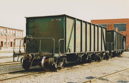
AC 8390 end view. At Steelton shops, August 1997. Blair Smith photo.

scan0030

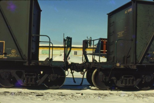
AC 8495 end details. March 1981. Photographer unknown, Chris vanderHeide collection.

Notice that the 8300 series car at top has a total of 5 end grabs plus the vertical grab mounted to the top chord, with the topmost end grab being almost directly below the vertical one, giving a doubled effect near the top of the car. The 8400 series car has 4 end grabs, without the grab nearest the top of the car.

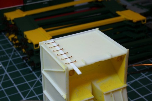
Compared to the model, the model is actually molded with locations for 6 grab irons. With the amount of cars I am working on, I decided it was not worth the amount of effort it would take to competely remove all of the molded bolt detail and the pre-molded drilling dimples and trying to make a template to re-drill it all to have 5 evenly spaced grabs instead of 6. (For the 8200/8300 series cars, or 4 (without the top one) for the 8400 series cars.) However, removing the detail for the top grab would provide that different visual detail between these two batches of cars. With the extra rung of the model, the spacing doesn’t quite work out perfectly, but the effect is close enough. For the 8400 series cars, I simply carefully carved away the bolt/drilling dimple detail for the top grab from the surface of the body and wet sanded the area with fine (1000-2000 grit) automotive finishing sandpaper.

The remaining dimples are all drilled out with a tiny #80 drill bit in a pin vise.

With the holes all drilled out, the grab irons can be installed. These are 18″ drop grabs. These formed wire details are available from several sources such as Tichy, Details Associates, Details West, etc. I place a drop of CA on a scrap piece of plastic and carefully dip the tails of the formed wire grab irons

To maintain a proper even depth for all the grabs, I use a piece of .030″ strip as a spacer when installing each grab:

IMG_8701

Using styrene spacer to install end grab irons.

When installing the grabs, cut the tails to length before installing; the open space inside the car end will be filled with the large metal weight that comes with the car, so these can’t extend into the interior. I trim the tails shorter before installation with a pair of flush cutters, and once installed and the glue is dried, finish off the interior with a few swipes of a flat needle file so the weight will sit properly into the cavity.

By comparison, the top grab is a straight 18″ grab. I used my calipers to line up the locations of the drill holes for the top grab with the end ladder and drilled them out as close to the edge of the strip as possible. This offsets the grab from the end and lines it up vertically with the end grabs. The grab is inserted (without trimming the tails in this case) from the bottom using tweezers and CAed in place, using my same .030″ spacer to obtain an even level on the grab. Once the CA sets, I cut the tails off with my flush cutters and file the ends of the wire flush with the top of the cap strip.

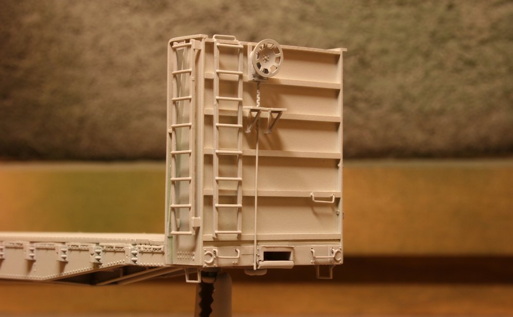
Here we can see both version of the car with the end and top grab irons installed; 8201-8400 series car at left, 8401-8500 series car at right:

IMG_8704

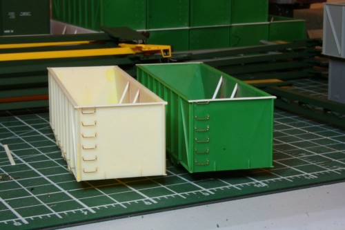
Finished grab irons. 8201-8400 series (left) and 8401-8500 series (right) versions.
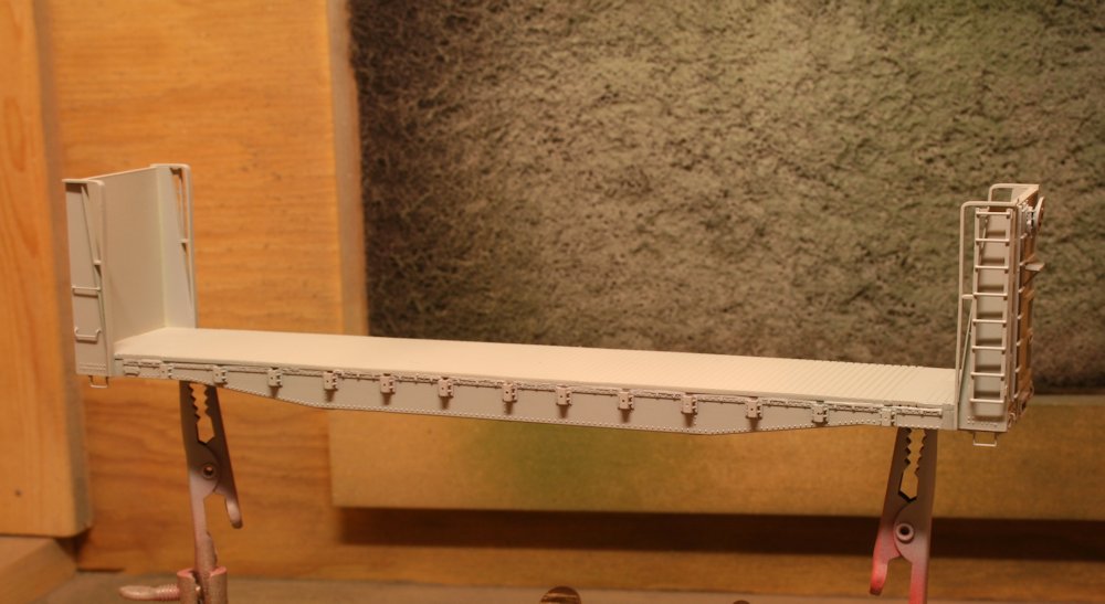
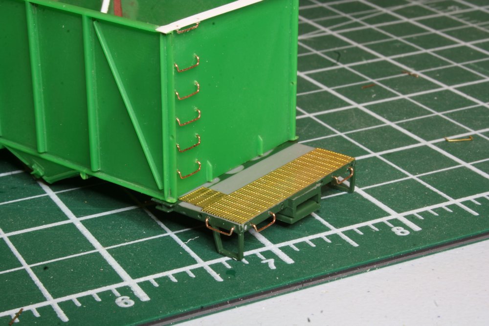
End Platforms

I’ve also been working on drilling and installing the grab irons on the end platforms of the car underframes. Nothing fancy here, just drill out the provided dimples and install the grab irons.

IMG_8706

Finished end and platform grabs.

All of the drilling was completed first; I’m working my way through installing the grab irons and that part is still in progress on the majority of the cars. About half a dozen of the bodies are complete so far. You might note in the backgrounds of the photos above that the deck grating on a large number of the frames still also needs to be completed yet, so it will still take a while to get all 25 cars completely up to this point, though I may progress some cars to the next point even while still catching up with some of the others.

This completes the major visible body detailing. The next major assemblies to figure out will be the altered end handrails for these cars, and the underframe detailing, which will be more or less installed as intended by the original kit and which should complete the assembly of these cars.