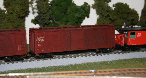
AC 3100 series wood boxcars from Accurail’s 40′ wood boxcar kit

This weekend I got back to working on a couple of assorted modeling projects that I’ve had on the workbench for a while. One of these is this trio of 40′ wood boxcars.

These models represent cars from a 100-car batch built in late 1927 numbered AC 3101-3200; by the late 1970s any of these cars still running would have been restricted to maintenance service; in 1970s-1980s freight car lists in the Official Railway Equipment Register the Algoma Central lists no boxcars in interchange service. My three cars will therefore likely spend the majority of their life parked in a side track with other maintenance equipment at Hawk Junction yard as material storage cars, or moving occasional OCS (“On Company Service”, i.e. non-revenue) cargos. Here’s a good prototype photo from Ted Ellis’s Algoma Central site of one of these cars in a work train at Frater (mile 102) in 1977:

http://algomacentral.railfan.net/images/AlgoCenRy/AC_3195_Frater_6-12-1977.jpg

These three cars were modelled using Accurail’s 40′ wood boxcar kit with wooden doors and ends. This kit is a pretty close match to the AC cars; they might not be 100% dead-on – I note some minor differences in the horizontal metal straping at the top of the vertical end braces, and the doors stops are located differently, but the side bracing looks pretty much the same – it’s close enough for me.

I chose not to do a lot of fine detailing on these cars; while Accurail’s details (i.e. grab irons and ladders) are molded onto the car body and not separately applied freestanding pieces, Accurail’s tooling is fairly well rendered, and on the wood car it’s not really bothering me that much. If it was a steel car, I’d probably upgrade the detail. Might seem a bit quirky, but in this case I can accept the level of detail of the car body.

The shells were actually painted quite some time ago; these were some of the first things I painted while practicing with my new airbrush. I sprayed the shells with CN Mineral Brown from TrueLine Trains; really any shade of generic “boxcar red”/freight car brown will do here.

Lettering is from a rub-on “dry transfer” lettering set from CDS Lettering. Following photographs, I deviated from the lettering set a little. The set includes horizontal lines above above and below the reporting marks (initials) and numbers. While when new these cars would have included those in their original lettering, all photographs from later years around the 1960s-80s show these cars without these lines. As I’m modeling this later period, these lines were excluded, and the reporting marks and numberes were moved up a bit, to put the reporting marks and number around the upper grab iron on the left side.

IMG_3892

Once all three cars were lettered, I weathered them up with Bragdon weathering powders applied with a stiff brush. I kept mostly to the darker browns – burnt umber and burnt sienna – as these are wood cars I avoided the oranger rusty colours. I also used a bit of black (soot) on the roof to darken it and accent the roof ribs; and also on the sides to darken and bring out the board detail of the sides. The Accurail car has a lot of grain molded into the sides and accenting this really gives the car a more worn appearance. I also tried concentrated the darked colours around the door opening and the end of the door track where rain would tend to wash off the car roof to try to make these areas a bit darker and more weather-worn. This wasn’t precision detailing, and it spreads out a lot by working it with the brush, and the effects of the powders are actually very subtle, but I think it did generally work to darken the general area just a bit. It’s not necessarily really consciously noticeable that those areas specifically have been darkened, but it brings out the details and the wood grain of the sides, and darkens and varies the colour of the car a bit. And on a couple of the cars even from a distance (maybe even more from a distance) the door and right side of the car is slightly darker in colour than the left side where the majority of the lettering is.

I then gave the three cars a quick spray of Dullcote last night to seal the lettering and weathering. Here’s a pair of the cars mounted back on their underframes and posed on my switching layout with one of my Overland cabooses:

IMG_7291

There’s a few details to be done yet, and the underframe needs some minor detailing and then the frame, trucks and wheels all need to be painted/weathered. The completed car will probably get some additional road weathering along the bottom at that time yet as well, but that’s another day.

Ideas for Adapting a Tonnage Rating for a Model Railway

Tonnage ratings are, put simply, a table of figures detailing the maximum tonnage a single locomotive of a particular type can handle across a railway or portion thereof. While certainly not the only consideration when applying power to a train (for example, in addition to tonnage ratings, some railroads may also specific a minimum horsepower per ton for specific trains, with priority fast freights given higher horsepower ratings to ensure quick movement), tonnage ratings are an important tool to make sure a train has at least the minimum amount of power (locomotives) to make it over the line.

Tonnage ratings are broken down by locomotive class (usually grouped by horsepower), and will vary on different portions of a railway based on ruling grades and curvature. The ratings are also listed separately in each direction over a portion of the railroad since uphill ruling grades will vary. For every class, there are three ratings listed, an A (best possible conditions), B and C (really miserable conditions like rain or ice making things really slippery) rating. The ratings are given on a per-unit basis; to know how much tonnage a particular consist can handle, you just add up the tonnage ratings for each unit for the overall rating.

Below are the actual ACR tonnage ratings copied from the 1982 summer employee’s timetable. It’s a bit of a dizzying wall of figures, and I’m not going to study the entire thing in detail, but the figures aren’t too difficult to interpret.

As a simple example, let’s say you have a 9000 ton train to haul from Hawk Junction to Hearst, and that conditions are good, so we’ll use the A rating. (We won’t worry about adding or dropping cars enroute.)

Looking at the table, we can see that a pair of SD40s will handle this nicely. (2units x 4620tons/unit = 9240)

However 2 GP38-2 units only have a combined tonnage rating of 6880, well under the 9000 tons we need to move, so we need a 3rd unit, which will bring the tonnage rating to 10320 if all three units are GP38-2s.

If all we have on hand are GP7s, 3 units at 2950tons/unit only gets us to 8850, so we’d need a fourth unit.

Of course we can mix and match units and just add up the tonnage ratings for each unit, the examples are just easier with similar units.

Table 1: ACR Tonnage Ratings from Timetable #139, May 29, 1982

GP7 GP9, GP38-2 SD40, SD40-2
A B C A B C A B C
Northward:
Steelton-Goulais 1600 1490 1440 1865 1740 1680 2510 2330 2260
Goulais-Frater 1250 1160 1125 1460 1350 1310 1960 1825 1765
Frater-Hawk 1500 1395 1350 1750 1625 1575 2350 2185 2115
Hawk-Hearst 2950 2745 2655 3440 3200 3100 4620 4300 4160
Southward:
Hearst-Hawk 3100 2890 2790 3615 3370 3255 4800 4450 4320
Hawk-Mekatina 1400 1300 1260 1630 1515 1470 2170 2020 1955
Mekatina-Goulais 1550 1440 1395 1810 1680 1625 2400 2230 2160
Goulais-Steelton 1650 1535 1485 1925 1790 1730 2560 2380 2305
Westward:
Hawk-Siderite 1350 1255 1215 1575 1465 1415 2120 1970 1910
Siderite-Brient 1800 1675 1620 2100 1955 1890 2820 2620 2540
Eastward:
Brient-Helen 1000 930 900 1165 1085 1050 1550 1440 1395
Helen-Hawk 1430 1330 1285 1670 1550 1500 2220 2065 2000

There are two things I’d like to draw your attention to in the table.

  • Note the extremely low numbers eastward out of Brient (Brient was the yard that served the harbour at Michipicoten, at the terminus of the Michipicoten branch), barely better than half of the westward ratings for the same portion. From the harbour at Michipicoten to Wawa is an almost continuous upgrade, and the steepest grades on the railroad are found near Brient on the descent to the Lake Superior shoreline, reaching 4% between the former Brient yard and Michipicoten.
  • Note also the huge disparity between the tonnage ratings north of Hawk Junction and the rest of the railway. North of Hawk Junction, and away from Lake Superior, the terrain flattens out considerably, and this is clearly reflecting in the more favourable tonnage ratings.

So where do we go from here?

The first thing is that these are tonnage (weight) ratings, not car counts. Unless your passion is number crunching, something that uses a simple car count instead of adding up differing tonnages for each car is probably a much preferable system for determining engines to train length.

The other issue is that on the model railroad, we try to weight our cars consistently so they operate well on our tighter-than prototypical curves and generally steeper than average grades (especially helices). There’s really not much of a difference between the weight of a load or empty.

While there have been articles published about methods scaling down prototype weights for the extra realism, and manipulating this table is actually kind of fun as an academic exercise, during an operating session I would prefer a quick an simple way of just looking at the train length to determine how many engines are required.

The simplest thing to do on a model railroad would be to take a representative unit, stick a bunch of cars behind it and run it up the ruling grade on the layout (quite likely the helix if your layout has one.) Find out how many cars a single unit can pull and use that as a baseline to say you can have, for example, up to ten cars per engine on a train. If your layout is flat, or your grades are very gentle, you might arbitrarily set your car counts to have something that looks good (or just not worry about it too much, and just say, “Yeah, that looks about right for this layout” – although really that’s pretty much the same thing, just without writing down an actual “rule” for it.) There’s not really a wrong way of doing it, as long as the engines can handle the size of the train.

Finally, model locomotives tend to be a lot more equivalent; a model SD40-2 isn’t twice as powerful as a model GP7; more likely they’re pretty equivalent. Depending on the brands or makes of the models, the GP7 could even be a better puller than the SD40! So to make the SD40s look more powerful, we institute an artificial restriction on the GP7s, maybe something as simple as “10 cars per 6-axle unit, 8 cars per 4-axle unit” to force the use of more smaller units to replace a pair of bigger ones, instead of having 2 GP7s do the same work as 2 SD40s.

The interesting thing about the ACR tonnage ratings is that huge disparity mentioned above between the flatter Northern subdivision north of Hawk Junction and the rest of the railway, which stays much closer to the rocky shores of Lake Superior. However, when I get to the point of actually building my ACR layout, which will be based on the Northern and Michipicoten subdivisions, I don’t imagine that grades on the (model) Northern sub. will be appreciably different than on the Michipicoten branch. In fact, depending on the layout design and inclusions of helices to double deck the layout or lengthen the run between stations, the ruling mainline grades could actually be between Hawk Junction and Hearst.

However the prototype tonnage ratings show that trains leaving Hawk Junction to the north should have a higher power/car ratio than trains heading south to Steelton (Sault Ste. Marie) or Wawa/Michipicoten. While the model version won’t really have the same characteristics, I can fake by decreeing artificially lower car counts/engine for the Michipicoten and Soo subdivisions. The last will likely just be staging, but trains leaving the modelled yard at Hawk Junction should “look right.”

As an exercise, I took the “A” rating column* for each class and divided the all the numbers by 125 tons. 125 tons is the approximate gross weight of a fully loaded 100 ton capacity car (like the ACR’s 100-ton open hoppers). But except for (loaded) ore trains, the average car in the 1980s was more like 70-ton capacity, and of course empties are much lighter. So this has the quite deliberate effect of already forcing car counts down.

* Since I probably won’t be modelling much of the Soo subdivision south of Hawk Junction, I only included north of Frater, and to simplify the Michipicoten branch, I split it at Wawa instead of Siderite, since Wawa and Michipicoten will probably be the only actually modelled locations on the branch.

The interesting thing about dividing by 125 (the weight of a loaded ore car) is that on the Michipicoten branch in the 1980s, the traffic was pretty much all loaded hoppers eastward, empties westward; so this actually gives a pretty good picture of the power required for loaded ore trains; 3 SD40s or 5 GP7s for a 36-car train of loaded hoppers. The westward car counts could actually be much higher since the cars would all be empties, but you also have to provide enough power to account for bringing the loaded train back!

After dividing by 125, I multiplied everything by .6 (somewhat less than 2/3) to scale things down a bit more, and simply rounded everything off to whole numbers. This already produces some interesting results, but some numbers are a bit high yet and may need to be artificially downgraded yet, but it’s an interesting place to start. Let’s take a look:

Table 2: “A” ratings, divided by 125tons and scaled down by .6

GP7 GP9, GP38-2 SD40, SD40-2
Northward:
Frater-Hawk 7 8 11
Hawk-Hearst 14 17 22
Southward:
Hearst-Hawk 14 17 23
Hawk-Frater 7 8 10
Westward:
Hawk-Wawa 6 8 10
Wawa-Michipicoten 9 10 14
Eastward:
Michipicoten-Wawa 5 6 7
Wawa-Hawk 7 8 11

This does some interesting things, which are easier to see with the smaller set of smaller numbers. The counts for the portion from Hawk Junction to Hearst are almost exactly double everything else, and things are pretty consistent in both directions, except between Wawa and Michipicoten where some really interesting things happen. Remember it’s basically entirely uphill from Michipicoten to Wawa.

Those Hawk-Hearst numbers remain pretty high, and now it’s really clear how much easier the north end of the railway is compared to the south. I don’t think a single model SD40 will handle 23 cars up a helix! I’ll need to limit things more on the Northern sub, so my ratios are never going to be quite double like the numbers above.

Here’s what happens when I scale everything a factor of one half, instead of .6:

Table 2: “A” ratings, divided by 125tons and scaled down by .5

GP7 GP9, GP38-2 SD40, SD40-2
Northward:
Frater-Hawk 6 7 9
Hawk-Hearst 12 14 18
Southward:
Hearst-Hawk 12 14 19
Hawk-Frater 6 7 9
Westward:
Hawk-Wawa 5 6 8
Wawa-Michipicoten 7 8 11
Eastward:
Michipicoten-Wawa 4 5 6
Wawa-Hawk 6 7 9

That produces something interesting. Just reading numbers off of this and using the same car counts in both directions pretty much gives max car counts of 12/14/18 (for GP7/GP38/SD40 respectively) between Hawk Junction and Hearst, and 6/7/9 everywhere else except for the extreme restrictions on the grade out of Michipicoten. But even that’s pretty reasonable: 3 SD40s handling a max of 18 cars (include the caboose in that) which is a decent sized train on a model railroad and would look pretty spiffy.

The Hawk-Hearst numbers will need to be scaled down more based on the realities of model locomotive performance, but the rest looks pretty reasonable, at least on paper.

Will I adopt these car limits as-is? Ultimately probably not exactly, but it’s an interesting place to start and hopefully something to generate some good discussion!

AC 8201-8500 series hoppers – Part 3: End platform grating

Here’s a good view of what the end of one of these cars looks like:

http://rrpicturearchives.net/showPicture.aspx?id=1251473

While the stock Walthers model basically just has some generic raised-tread pattern on the end, you can see that the pattern of walkway grating is quite distinctive, and I wanted to capture this.

The following wreck photo also highlights quite clearly how the grating is open, and would be see-through:

http://algomacentral.railfan.net/images/AlgoCenRy/AC_Mile_5_wrk-5_5-14-1980.jpg

If I were only doing one of these cars, I might consider completely cutting away the end platforms and rebuilding them from scratch to have the open grating, however for the sheer volume of these cars that I need, I’ve decided this would be far too much time and effort to be worth it.

I do however wish to at least replicate the tread pattern, which is a big difference from the model. To this end, after disassembling the cars and removing the handrail pieces, I filed the top surface of the end platforms smooth to remove the existing tread texture.

IMG_6616

End platform filed smooth.

I cut the new walkways out of etched brass walkway/grating material. The walkways are a rectangular “Apex” tread pattern. I’ve been using etched brass material from Details Associates. I just used a regular pair of scissors to cut the thin brass sheet.

There’s two parts to the walkway tread on these cars. There’s the grating on the open area of the platform, and an extra bit of grating leading to the end ladder. The platform grating is cut out of the etched material in a rectangle 2.5 by 10.75 scale feet in size. The cut piece should all be whole rectangles, with the “grain” following the width of the car.

The walkway to the end ladder grabs is oriented perpendicular to the platform grating. With the sizing of the rectangles in the Details Associates etching, I cut a strip from the etched sheet 3 rectangles wide; this is perfectly the size to fit between the platform grating and the car body. I then cut these into approx. 1.75 scale foot pieces.

With all the piece cut, I attached them to the prepared underframe pieces using CA adhesive. Very carefully, trying not to glue my fingers to themselves or the car, I used a toothpick to spread the CA across the bottom surface of the grating, and then applied the grating material to the car. For the smaller pieces I used a pair of curved tweezers to move them into position.

IMG_7289

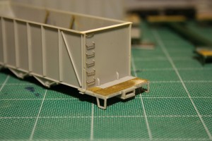
Several finished platforms, with one just filed smooth in the middle.

IMG_7290

Completed walkway/platform grating with the underframe and body fitted together, showing how the walkway accesses the end ladder.

This is the current point I’m at with these cars (well, the 9 I’m [semi-]actively working on). 5 cars now have the grating complete (I just finished a few of them up tonight) and another 4 have the platforms filed and prepared (and actually have for quite some time now).

After I finish this current batch of cars, (I’m hoping to try to bring these 9 all the way through to completion now) I’ve got another 50 or so of these Walthers cars waiting for the same treatment at some point!

ex-Troop Sleeper Baggage Cars – Part 3: Plugging windows

The next step with these cars involves plating over the carbody vents and the unwanted windows. The upper vents were all plated over on these cars, but the windows varied from car to car, and were done later. Up until the late 1960s and probably into the early 1970s, the cars all would have had their original windows still. In the 1970s however, some of the cars started to have windows blanked out and plated over when they received a full shopping.

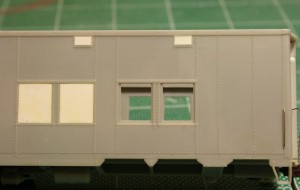
The car I’m currently working on represents AC 306 (ex-AC 205, ex-US Army 7883). Photos I’ve collected from various sources online show that on one side of the car, 3 windows (2 to the right and 1 to the left of the baggage door) were plated over, while on the opposite side, only one window to the right of the door was plated.

Note that the windows I’m referring to here are all in the first double pair of windows; the original troop sleepers have a single window on either side of the original entry door, but both of these windows and the original man door are overlapping with the space where the baggage car door will go. Those windows will need to be completely gone, not just plated over with the frame still in place. That’s a little bit more involved, so I’m leaving that until later.

I plated the required windows quite simply by cutting rectangles of .010″ styrene sheet to fit the window openings. (Actually I cut this just slightly oversize and then carefully file down the edges so that it fits in perfectly.) When you look at the windows on the model, you can see the riveted frame around the window, and then an inset window sash, which on the rear car would have been the moveable part of the window. To plate over the window, I just cut the plate to fit just inside the outer frame, and lay down on top of the recessed sash. The .010″ thickness of the styrene sheet set on top of the recessed sash perfectly represents the plated over opening.

IMG_7186

Car with upper vents and two windows at left plated over. The two windows at right will remain open and receive the original kit window glass pieces when the car is fully completed.

Similarly the vents along the top of the car body were also plugged with .010″ material but in this case their narrow width meant a 010″x.080″ strip cut to length will fit perfectly in the vent opening. Again the recessed depth is such that a .010″ strip is almost perfectly flush.

That takes care of the easy part of the car side modifications; cutting out the door, removing the single windows and smoothing everything up again will be considerably more invasive surgery.

ex-Troop Sleeper Baggage Cars – Part 2: Doors

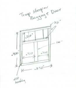
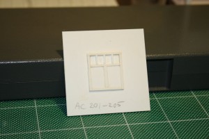
The doors for these cars was an interesting scratchbuild project. It’s been a while since I worked out the measurements, but I was able to come up with something that looks pretty good. Here’s my drawing from my notes:

baggagedoor

Measured construction drawing of the baggage car door.

The scratchbuilt door master consists of a .020″ styrene door blank with the trimming made from scale 1″x6″ strip (except for the centre vertical that divides the lower part of the door into 2 panels with is a little wider – 1″x8″. Working carefully and measuring with my dial calipers, the trim was fixed by applying liquid styrene cement with a fine brush. My favourite here is the Testors liquid plastic cement. I highly recommend against Plastruct’s Plastic Weld in this application as I’ve found it to leave a nasty surface residue when used on styrene.

To get a nice clean upper window, I applied the trimming to the door blank before cutting out the opening. I don’t remember doing the cutting anymore, but the best approach would be to drill out the corners and then play “connect-the-dots” to cut out the rough opening. What I definitely do remember is carefully opening up the window opening with a series of fine needle files, filing the opening even with the 1×6 trim strips.

Since I knew I wanted to probably make more than one of these cars, I planned on making one door master which I could then make molds from to cast several copies in resin. The door blank was therefore cemented to a piece of .060″ styrene backing.

The window mullins were added after the door was cemented to the backing plate. This ensured that they were nice and flush. The mullins are .030x.040″ strips, laying on their wide side to match the ~.030 thickness of the .020″ door + 1×6 (.011″x.066″) trimming. These should be evenly spaced. (I didn’t keep notes for this spacing, but measuring the door master shows each window pane to be an average of .145″ wide (within a variance of .005″, well within a margin of error and not detectable by the eye).

IMG_1015

Finished door master.

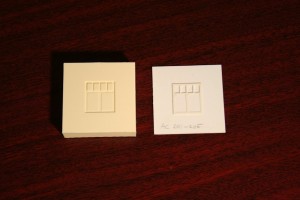
Following the completion of the master, I was able to create the rubber mold from the master and use it to cast several copies of the door. I now have more than enough doors to do several cars.

IMG_1249

Rubber mold and scratchbuilt door master.