CP Woodchip Boxcar – 6′ Chip Doors

In the late 1970s and early 1980s, Canadian Pacific converted several hundred old 40′ boxcars into woodchip gondolas via the simple expedient of cutting away the roofs of the cars. While there were some variations (including some older International of Maine conversions that had the height of the sides extended and doors widened to 8′) the standard conversion in the 1980s was a simple 40′ boxcar with standard 6′ door with the roof cut away and the original sliding doors replaced with a two-piece hinged wooden door.

Source cars for these conversions were drawn from various different original series, and there’s a lot of variation in these converted cars.

The mill at Dubreuilville shipped out large amounts of woodchips in cars supplied by Canadian Pacific to pulp mills along the Lake Superior north shore at Marathon or Terrace Bay. So I can use a collection of CP woodchip service cars for this traffic. The ACR would have handled these cars just the short distance between Dubreuilville and Franz. Extra empties were apparently typically stored in the siding at Wanda, between Dubreuilville and Franz.

IMG_8765

This car is a Intermountain kit for a Pullman-Standard “PS-1” 40′ boxcar. (“PS-1” was actually Pullman-Standard’s catalog designation for ANY boxcar they produced, although model railroaders have (somewhat erroneously) come to associate the term with just Pullman-Standard’s earlier post-war designs.) The body details are assembled pretty much as according to the kit although the roof and doors are left out.

IMG_8768

The main visual feature of the car (apart from the missing roof) is the new chip doors, which necessitated the scratchbuilding of said doors from styrene.

The new door is a piece of .020″ styrene sheet cut to fit the door opening, trimmed with .010″x.060″ strip for the edges of the door panel. The horizontal door locking bar and the “mounting pads” under the hinges are pieces of .010″x.040″ strip. The flat parts of the door hinges are represented by pieces of .005″ styrene, basically eyeballed and cut with a razor blade, and the actual hinge parts at the edge of the door, and the vertical locking bar at the top of the door are bits of thin brass wire.

The bottom hinge plate at the foot of the door is a piece of .015″x.156″ strip with a .020″x.020″ trim piece along the top.

IMG_8769

Because the car is open, and thus has little or no way to hide any weight, I inserted a styrene false floor into the car which hides a thin layer of sheet lead flashing to give the car weight.

IMG_8771

The roofs on most of these cars were removed simply by torching out the panels in between the roof ribs (carlines). Most of these cars kept these ribs in place to hold the car together, but over time these got banged up and damaged and cars would be missing many of them. I used T-section styrene shapes to make a representation of these remaining roof ribs, leaving several out as “missing”.

This pretty much completes the major details of this particular car; next step is painting.

Scratchbuilt Boxcar Tack Boards

I spent some time this nice Sunday afternoon trying to catch up on some minor projects that have been languishing in a state of near-completion, or nearly-ready-for-the-paint-shop.

One of these projects was a pair of 50′ boxcars from Intermountain’s 50′ PS-1 boxcar kit. The one thing I didn’t really like about this otherwise excellent kit was the tackboards for the doors. (For the uninitiated, these are wooden boards mounted on or near the doors and the ends of the cars to which hazardous materials placards, or unloading or routing instruction cards could be stapled.) These tackboards generally consist of several wooden boards in a metal frame, and are usually mounted on the door of the car (for sliding door cars) or sometimes just beside the door on plug door cars.

The Intermountain kit part for the tack board has a really wide gap between the boards, which just doesn’t look right to me, so this project has been waiting on the sidelines for me to make new ones. Well, today finally I did.

This is a simple project; the tackboards themselves are 3 strips of HO scale 2″x6″ styrene cemented side by side, with the frame represented by a piece of 2×3 at each end. The 2×3 is cemented to the main 2×6 pieces such that it stands on edge, to give a little relief to the frame.

Here’s my scratchbuilt tack boards (enough for 2 cars) compared to the original Intermountain kit parts:

IMG_8755

I simply find the dividing lines on the Intermountain part way too coarse. Which is odd, because I was perfectly happy with the tack board parts on several Intermountain 40′ kits I have, and you’d expect them to be similar within the product line.

The smaller tack boards were similarly done, with the centre board made from a single piece of 2×6.


I also got a couple of 40′ boxcar kits just about ready for the paint shop, hopefully I’ll have a chance to do some spraying tomorrow evening.

AC 8201-8500 Series Hoppers – Part 4: Grab Irons

Over the last few weeks I’ve been slowly working on this hopper project again, drilling out the myriad holes for the car body grab irons. This project languished for a while as I didn’t have any #80 drill bits (darn things are so easy to break!) so I had to order a few, and I’ve just been pretty busy through the last couple of months with the December holiday season and other things. However a week or two after New Year’s I got my order of fresh drill bits, and I’m trying to deliberately spend a little time at least one or two nights a week on projects. Of course the primary project I’ve started to get back into is my 25 car batch of hoppers where each step of progress takes a bit of time due to the volume of cars being worked on at the same time. And drilling out that many small holes on 25 bodies and frames has taken a few weeks to complete. So that has accounted for my dearth of recent updates. However I am trying to get some momentum going again, and hopefully get some other smaller projects finished off as well.

So, without further ado, back to the hopper project! Over the years this model has moved between different product lines at Walthers: first their standard line, then “Gold Line” with metal wheels, then “Platinum Line” which have wire grab irons factory installed. (And I think with the latest release(s) the model has been shifted again into the “Proto” series (the old Proto 2000 line inherited from Life-Like), although I really don’t think this model belongs in that category.) Earlier releases before the models were upgraded to the “Platinum” line did not have grab irons installed. I’ve been collecting these cars for quite a while now (and grabbing cheaper pre-“Platinum” cars at shows and on eBay to build up the fleet) so I have a lot of both.

Body Grabs

A bit of comparison of prototype photos to the model reveals a couple of interesting minor details.

First, the prototype AC cars have an additional grab mounted off the top cap on the end (which of course the model does not have, and which I discussed in an earlier post).

Secondly, when comparing end photos of the first batch of cars (AC 8201-8400) to the second batch (AC 8401-8500), notice that the first series has one extra grab iron compared to the later series:

ACR From Blair 012

AC 8390 end view. At Steelton shops, August 1997. Blair Smith photo.

scan0030

AC 8495 end details. March 1981. Photographer unknown, Chris vanderHeide collection.

Notice that the 8300 series car at top has a total of 5 end grabs plus the vertical grab mounted to the top chord, with the topmost end grab being almost directly below the vertical one, giving a doubled effect near the top of the car. The 8400 series car has 4 end grabs, without the grab nearest the top of the car.

Compared to the model, the model is actually molded with locations for 6 grab irons. With the amount of cars I am working on, I decided it was not worth the amount of effort it would take to competely remove all of the molded bolt detail and the pre-molded drilling dimples and trying to make a template to re-drill it all to have 5 evenly spaced grabs instead of 6. (For the 8200/8300 series cars, or 4 (without the top one) for the 8400 series cars.) However, removing the detail for the top grab would provide that different visual detail between these two batches of cars. With the extra rung of the model, the spacing doesn’t quite work out perfectly, but the effect is close enough. For the 8400 series cars, I simply carefully carved away the bolt/drilling dimple detail for the top grab from the surface of the body and wet sanded the area with fine (1000-2000 grit) automotive finishing sandpaper.

The remaining dimples are all drilled out with a tiny #80 drill bit in a pin vise.

With the holes all drilled out, the grab irons can be installed. These are 18″ drop grabs. These formed wire details are available from several sources such as Tichy, Details Associates, Details West, etc. I place a drop of CA on a scrap piece of plastic and carefully dip the tails of the formed wire grab irons

To maintain a proper even depth for all the grabs, I use a piece of .030″ strip as a spacer when installing each grab:

IMG_8701

Using styrene spacer to install end grab irons.

When installing the grabs, cut the tails to length before installing; the open space inside the car end will be filled with the large metal weight that comes with the car, so these can’t extend into the interior. I trim the tails shorter before installation with a pair of flush cutters, and once installed and the glue is dried, finish off the interior with a few swipes of a flat needle file so the weight will sit properly into the cavity.

By comparison, the top grab is a straight 18″ grab. I used my calipers to line up the locations of the drill holes for the top grab with the end ladder and drilled them out as close to the edge of the strip as possible. This offsets the grab from the end and lines it up vertically with the end grabs. The grab is inserted (without trimming the tails in this case) from the bottom using tweezers and CAed in place, using my same .030″ spacer to obtain an even level on the grab. Once the CA sets, I cut the tails off with my flush cutters and file the ends of the wire flush with the top of the cap strip.

Here we can see both version of the car with the end and top grab irons installed; 8201-8400 series car at left, 8401-8500 series car at right:

IMG_8704

Finished grab irons. 8201-8400 series (left) and 8401-8500 series (right) versions.

End Platforms

I’ve also been working on drilling and installing the grab irons on the end platforms of the car underframes. Nothing fancy here, just drill out the provided dimples and install the grab irons.

IMG_8706

Finished end and platform grabs.

All of the drilling was completed first; I’m working my way through installing the grab irons and that part is still in progress on the majority of the cars. About half a dozen of the bodies are complete so far. You might note in the backgrounds of the photos above that the deck grating on a large number of the frames still also needs to be completed yet, so it will still take a while to get all 25 cars completely up to this point, though I may progress some cars to the next point even while still catching up with some of the others.

This completes the major visible body detailing. The next major assemblies to figure out will be the altered end handrails for these cars, and the underframe detailing, which will be more or less installed as intended by the original kit and which should complete the assembly of these cars.

Rapido FP9A Arrived

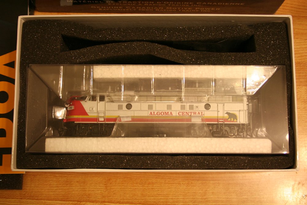
Today I got a package in the mail from my dealer containing one of the new Rapido FP9A locomotives factory decorated for Algoma Central #1750. Acquired by WC in 1995 for the ACR passenger trains, it’s a little completely out of my era, but I just “had” to collect a couple of Rapido’s models to put together a “modern” (1995-2000) version of the ACR’s regular passenger train. It’ll mostly reside on a display shelf, but be fun to run through every once in a while.

IMG_8608

In the box, with solid protective packaging.

The model comes packed in a protective plastic holder that securely wraps around the engine and holds it tightly, and did a good job of protecting it from any damage in shipping. Every little bit and piece appeared to be completely intact.

IMG_8614

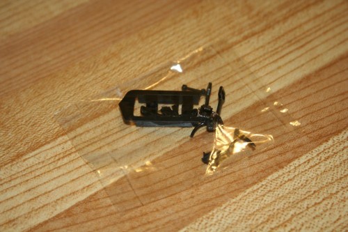
Additional parts bag.

Little parts baggy including extra re-rail frogs, steam line connections and extra couplers and a part for a rear diaphraghm. The AC units didn’t have them (and neither did the majority of the old CN units, and many that did had them removed later), so that piece won’t need to be installed.

IMG_8620

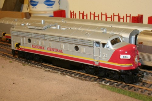
The model, out of the box!

Here’s the model taken out of the box and set on the rails of my in-progress switching layout. You’ll have to excuse the background and the quality of some of these photos; this small layout isn’t very finished and the lighting in this room isn’t the best.

ACR From Blair 015

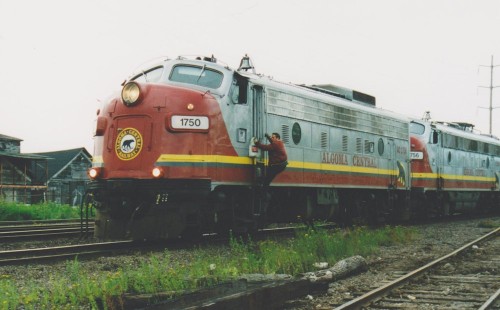
The real 1750 arriving at Steelton Yard on the head of the southbound Agawa Canyon Tour Train. Blair Smith photo, August 1996.

IMG_8625

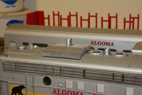
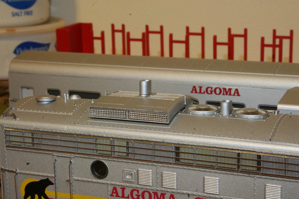
Winterization hatch detail, with stack extension.

The model has a lot of gorgeous detail, although a couple of things stuck out. On the large winterization hatch over the radiator fans, there’s a tall exhaust stack extension which doesn’t appear to have been present on the AC units. This may have been applied at some point in the past to the CN units that eventually (by way of VIA) became AC 1750 and 1751, but weren’t there under ACR ownership. Fortunately with a bit of firm but careful pressure, this stack extension can be pulled out. The hatch also doesn’t appear to be quite fully seated all the way down on the close side, but this should be fixable.

IMG_8627

Rear detail, also showing exhaust stack extension removed. The back-up light to the left of the door lights up when the engine is set in reverse.

Since I got the DCC/Sound version, naturally I wanted to get the locomotive fired up on the NCE PowerCab I’m powering the switching layout with. At first – nothing happened. I checked the manual with the model, and the text indicated that the decoders are set by default to address “3”. (3 is the standard default address for a decoder, but I kind of expected the installed decoder to be set to the model’s road number in this case. No big deal, reprogramming a decoder address is a pretty standard task.) Once I was able to select and send a command to the engine, a quick tap of the F8 function key on the throttle (Function 8 is the standard mute/un-mute function for most sound decoders) brought the sound to life. The sound sounded quite agreeably like the EMD 567 engine in the FP9, which it well should – Rapido has a couple of videos on their YouTube channel of their antics in recording the actual sounds off a pair of real FP9s on a tourist railroad in the US. The sound volumes will probably eventually be adjusted down, but aren’t nearly as loud as many other sound decoders are on their factory settings, which usually seem to be set to “max”, when 25-50% level would probably sound much better.

I haven’t quite finished the points on several switches on this layout, so I was only able to run the engine back and forth about a foot or two. It seemed to run reasonably well (although it was a little jerky on speed step 1, but smoother on step 2), and the sound revved up and down nicely, but I think I’ll need to take it out to the club layout sometime to really give it a good breaking in.

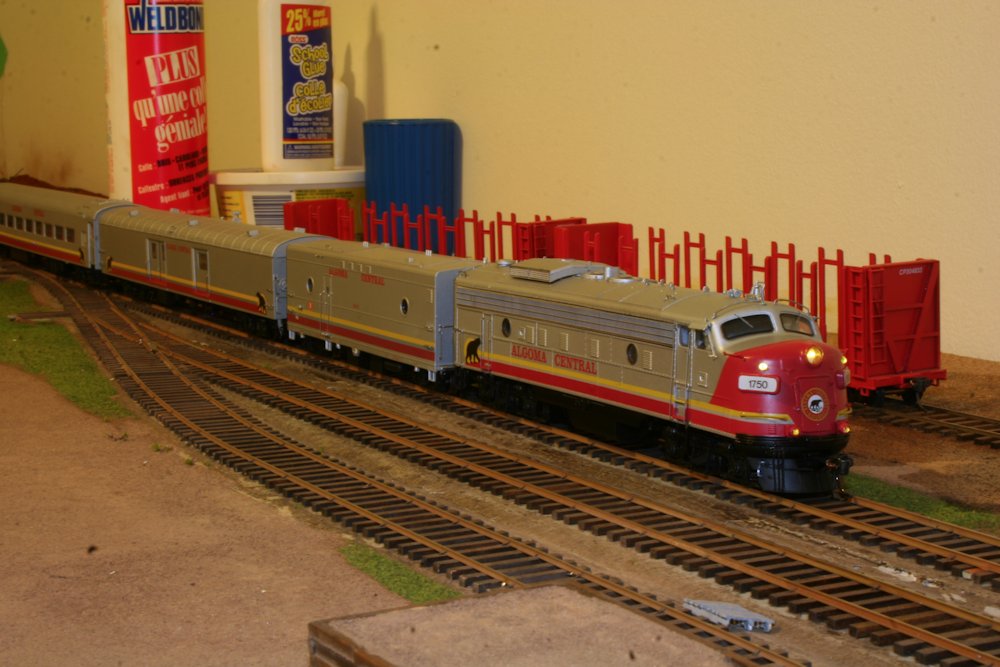
The engine has some nice lighting functions as well. Headlight and ditch lights are independently controllable, as are the class lights and numberboard lights (although the numberboards end up being just about as bright as the headlight). The headlight, ditch lights and numberboards appeared to have a slight greenish tint to them, when I’d prefer a more “natural” incandesant-looking warm yellow. Note sure yet if I’ll look at possibly replacing the LEDs used.

IMG_8626

Powered up with headlights, ditch lights and white class lights lit. Numberboards are also able to independently light up, but turned off in this photo.

The class lights lit up nice and bright white; the instructions indicated that the F10 function should switch them between Off, White and Green, but I seemed to only be getting them rotating between Off and White. No green. Not sure if I did something wrong, or if it’s something in the programming setup of the decoder, but it’s not too likely that I’ll ever be running this particular unit on the head of a train with additional sections following.

(Edit: Jason from Rapido pointed out in a comment that the decoder on this model is changed and the white and green lights are separately controlled on F10 and F11. This was actually indicated on a technical reference insert sheet for the decoder, which I hadn’t closely read at the time as I didn’t realize the functions would be mapped differently from the information in the original instruction manual for the FP9s.)

IMG_8629

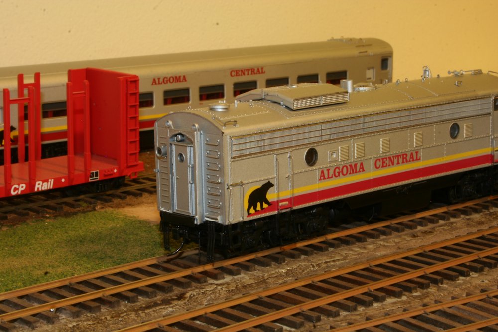
A full set of Rapido Algoma Central passenger equipment: FP9A locomotive, steam generator car, baggage car and coach.

The silver paint on the locomotive is a good match to the shade used on Rapido’s previous offerings: the steam generator car, baggage car and second run of coaches (the original run of AC coaches came out in an odd tan colour, which was changed for the later run(s)). With one of each, it makes a nice solid train.

The lettering and decoration looks pretty good. The model does not have the reporting marks and numbers on the sides near the rear – these were added a little bit later, not when they were originally painted, so it’s not inaccurate, although the units would have spent more of their lives with the numbers than without. So it might have been nice if the side numbers were included, or if a small decal sheet with the numbers was included so modellers could choose. Since I actually model the 1980s, I’m not running this set as any particular year, but it is something that some might wish to note.

Postscript:

Included in the box was a flyer for Rapido’s upcoming CN/VIA F9B models. The fine print at the bottom is a classic example of the geeky institutional humour brought by Rapido’s founder and owner, Jason Shron:

IMG_8612

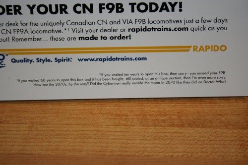
Always read the fine print…

25 Hopper Interiors Completed

Slowly but surely over the last few weeks I’ve been working on completing the interior detailing on all of the Walthers hoppers I’ve stripped so far. That’s a total of 25 cars currently in progress at the same time. (This actually represents a little under half my current fleet of these cars.)

These twenty-five cars now have the interior bracing and the treatment to the top chord completed. I explain the modifications a bit more in this previous post, but the process basically involves patching the holes on the inside of the body (where the solid bulkhead part from the stock model was fitted) with body putty, adding the extended lip over the end of the car, filing the top of the sides smooth, instead of the peaked side on the model representing an angle iron for stiffening, and finally installing the new interior bracing. On the older cars I did, I fashioned the bracing from .040″ brass wire, but I’ve now taken to using 3/64″ (.047″) styrene rod from Evergreen to make these, as it’s far easier to file and work with, and the welded styrene-styrene bond is stronger and more flexible than the brittle CA bond to glue the brass to the plastic body.

IMG_8562 IMG_8563

Now i just need to get the other twenty end platforms all up to the same point…