AC 8201-8500 series hoppers – Part 3: End platform grating

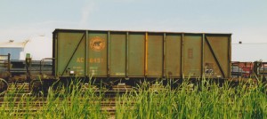
Here’s a good view of what the end of one of these cars looks like:

http://rrpicturearchives.net/showPicture.aspx?id=1251473

While the stock Walthers model basically just has some generic raised-tread pattern on the end, you can see that the pattern of walkway grating is quite distinctive, and I wanted to capture this.

The following wreck photo also highlights quite clearly how the grating is open, and would be see-through:

http://algomacentral.railfan.net/images/AlgoCenRy/AC_Mile_5_wrk-5_5-14-1980.jpg

If I were only doing one of these cars, I might consider completely cutting away the end platforms and rebuilding them from scratch to have the open grating, however for the sheer volume of these cars that I need, I’ve decided this would be far too much time and effort to be worth it.

I do however wish to at least replicate the tread pattern, which is a big difference from the model. To this end, after disassembling the cars and removing the handrail pieces, I filed the top surface of the end platforms smooth to remove the existing tread texture.

IMG_6616

End platform filed smooth.

I cut the new walkways out of etched brass walkway/grating material. The walkways are a rectangular “Apex” tread pattern. I’ve been using etched brass material from Details Associates. I just used a regular pair of scissors to cut the thin brass sheet.

There’s two parts to the walkway tread on these cars. There’s the grating on the open area of the platform, and an extra bit of grating leading to the end ladder. The platform grating is cut out of the etched material in a rectangle 2.5 by 10.75 scale feet in size. The cut piece should all be whole rectangles, with the “grain” following the width of the car.

The walkway to the end ladder grabs is oriented perpendicular to the platform grating. With the sizing of the rectangles in the Details Associates etching, I cut a strip from the etched sheet 3 rectangles wide; this is perfectly the size to fit between the platform grating and the car body. I then cut these into approx. 1.75 scale foot pieces.

With all the piece cut, I attached them to the prepared underframe pieces using CA adhesive. Very carefully, trying not to glue my fingers to themselves or the car, I used a toothpick to spread the CA across the bottom surface of the grating, and then applied the grating material to the car. For the smaller pieces I used a pair of curved tweezers to move them into position.
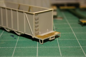
IMG_7289

Several finished platforms, with one just filed smooth in the middle.

IMG_7290

Completed walkway/platform grating with the underframe and body fitted together, showing how the walkway accesses the end ladder.

This is the current point I’m at with these cars (well, the 9 I’m [semi-]actively working on). 5 cars now have the grating complete (I just finished a few of them up tonight) and another 4 have the platforms filed and prepared (and actually have for quite some time now).

After I finish this current batch of cars, (I’m hoping to try to bring these 9 all the way through to completion now) I’ve got another 50 or so of these Walthers cars waiting for the same treatment at some point!

AC 8201-8500 series hoppers – Part 2: Interior and Top Chord

So in my previous post, I introduced this project and the prototype for these cars, 300 cars built by NSC to an Ortner design in 1974-75. Walthers makes an HO model of the Ortner design, which makes a convenient start to this project. Of course there are some details, both major and minor, that differ between the Walthers model and the AC prototype cars.

IMG_6612

Stock Walthers model without the hokey included aggregate load.

The biggest change that needs to happen is that the AC cars have tubular V-bracing between the bays, not the solid bulkheads that the model has. This takes a little bit of work, but is not difficult, and you’ll agree this makes a huge difference in appearance.

If you only want to do minimum changes or detailing to turn the Walthers car into a reasonably accurate AC car, this is the change to make. Also, since the insides of the cars were unpainted steel, this change can be done on a factory painted car while completely preserving the factory lettering, as the inside of the car should be masked and repainted a rusty colour.

The first step is the easiest, just take out the removeable bulkhead pieces and throw them away. (Or, toss them in the scrapbox. A good model railroader is a pack rat; you never know when that oddball useless leftover part now can be repurposed for something completely unintended later. Or at the very least chopped up into smaller pieces or used as part of a steel scrap load or junkyard scene.) Then I fill the holes left behind with modeling putty. Most of the cars I’ve been working on so far I’ve filled the holes using either Tamiya or Squadron putties. Other modelers also recommend Bondo putty from the automotive department, and I’ll probably try that in the future. Canadian Tire is a lot more convenient than the local hobby shops that are an hour+ away.

SAMSUNG DIGIMAX 360

Several cars in progress.

Once the body putty has had a day to cure, I file it down even with the inside surface of the sides and sand it smooth with progressively finer sandpapers. Once again the automotive aisle at Canadian Tire is rather handy here as a source for 1000+ grit finishing/polishing sandpapers to get a nice smooth interior side.

Smoothing out the bottom of the bays is a bit more tricky with the angled geometries, so I just did the best I could. A sanding stick from the hobby shop gets a good start here.

sandstick1

I used a sanding stick like this one on the inside of the bays.

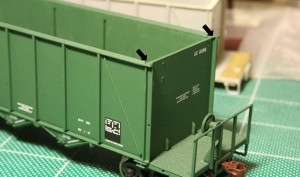
Now, before I move on to installing the interior bracing, I finish cleaning up the top of the car body. (Or this part can really be done first.) The AC cars have an overhanging lip over the top of the car end that the model doesn’t have. I modeled this simply using an HO scale 2″x6″ styrene strip across the top of the end. First, however, two little angle pieces need to be carved off the top of the corners on the model and filed flush with the top of the end, as indicated in the below photo marked with arrows:

IMG_6983

Remove corner detail on top surface at points indicated to allow 2×6 header to be installed.

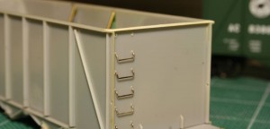
Once this detail is removed and smoothed down, the end cap is installed. I simply cut a piece of styrene 2×6 to length and cement it to the top of the edge. Once the end cap has been installed and the cement has set, I file down the angled top chord on the model flush all the way around with the top of the 2×6 end cap.

IMG_6986

End cap installed. End handgrabs are partially installed on this car.

Once the sides are finished, the interior bracing can be installed.

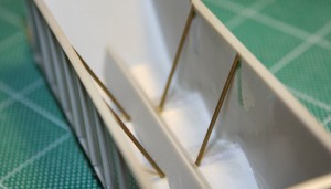
I made the braces from .040″ brass rod/wire. The rod is cut to length (approx. 1.20″) and I file one end off at an acute angle so that it rests properly against the side. Test fit this several times before glueing in place.

I drilled a small hole right next the the centre sill of the car between the bays to accept the bottom end of the brace. Then I simply use a drop of CA glue to secure both ends of the brace.

IMG_6618

Interior bracing.

AC 8201-8500 series hoppers – Part 1A: Ballast variation

S3600332.jpg

AC 8331 at Steelton Yard in 2004. Chris vanderHeide photo.

One interesting variation on these cars was a series of 10 cars, AC 8330-8339 that were rebuilt in the early 1990s with side-discharge gates suitable for ballast service.*

You can see the marks on the side of the car where the modified slope sheets have been welded to the sides, so you can see how the inside of the car peaks in the middle.

This would certainly be a neat variation to model, and an interesting kitbash, although this is several years outside of my modeling time frame of 1985.

Has anyone reading this blog ever modeled a similar sort of ballast service rebuild?

*I’ve seen video however from the early-mid 1990s of a couple of these rebuilds mixed right in with other hoppers on the branch train to Wawa/Michipicoten. It seems they were still used in regular service when not used for ballast service.

AC 8201-8500 series hoppers – Part 1: Background and Prototype Information

These big, forest-green 100-ton capacity rapid discharge hoppers were a distinctive sight on the Algoma Central; and at a total of 300 cars built to this design in 1974-75, formed the largest part of the Algoma Central’s hopper fleet during the 1980s. These cars replaced aging 55 to 70-ton twin hoppers that had build dates ranging around World War I.

ac8422detail2

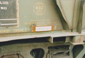
Builder’s stencil on AC 8422. Blair Smith photo.

These 300 cars were built by National Steel Car of Hamilton, ON using a design licensed from Ortner Freight Car Co. of Cincinatti, OH. The cars were built and delivered in two batches:

ac8376

AC 8376. Blair Smith photo.

AC 8201-8400 built from January into April of 1974.

ac8451

AC 8451. Blair Smith photo.

AC 8401-8500 built from January to February of 1975.

Both series are visually identical except that the middle rib on all of the cars in the second batch was painted yellow. The significance of this is a little vague; it certainly did not indicate an assigned service, as all of the Algoma Central’s hopper cars mixed together freely, and the only hopper traffic the ACR handled was all related to the iron ore processing plant at Wawa (including hauling limestone, coke and other ore fines from the harbour at Michipicoten to Wawa), and shipping this output south to the Algoma Steel mill at Sault Ste. Marie.

IMG_6612

Stock Walthers “Platinum Line” Ortner hopper in AC lettering.

Fortunately, Walthers has produced a model of the Ortner design that NSC licensed, so modelling these cars is relatively straightforward, although there are some minor differences between the NSC and Ortner versions. (Of course.) Many of these are pretty minor, and most modelers may choose to ignore them, but I wanted to capture some of the signature flavour of these NSC clones. Also, as Walthers has these cars available in AC paint and lettering, some may wish to avoid repainting as much of the car as possible. (Unfortunately however there are some errors and deficiencies in the Walthers lettering; I’ll go over these in more detail when I discuss painting and lettering the models, but for now I will just mention that a decal set is available from Black Cat Decals that can be used to correct the lettering or fully repaint and re-letter the Walthers car.)

The main difference between the AC prototypes and the Walthers model is the most visible, and this is one that any serious AC modeler will really want to change. The Walthers model comes with a pair of solid bulkheads dividing the car into three separate bays, while the prototype cars were fully open like most standard hoppers with V-shaped tubular structural bracing in between the bays.

Other minor differences involve the handrails and the top cap of the end of the cars; this will be discussed in detail when I discuss how I model these changes in upcoming posts in this series.

That’s about it for the intro; coming up – modifying the interior of the cars.