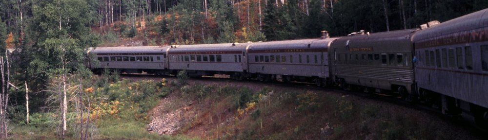
One of the signature scenes that I plan to include on my eventual ACR layout is the Algoma Ore Properties sinter plant and ACR yard at Wawa, Ontario. Built in 1939 and expanded and upgraded many times over the next five decades, the sinter plant at Wawa upgraded the iron ore mined at nearby mines in the so called Michipicoten Iron Range in which the community of Wawa is located. The processed ore was then shipped south via the ACR to supply the Algoma Steel blast furnaces at Sault Ste. Marie.
Along with the heavy industrial facility of the AOP plant, two other key structures to model at Wawa would of course be the Algoma Central station and freight house. I knew that modelling the station had just become easier a few years ago when I arranged access to view certain archival materials at the public library in Sault Ste. Marie during my 2014 visit. One of the items listed in the inventory was “Plans for Jamestown Station Building”. (During the 1950s there was an attempt to renamed the station and community “Jamestown” in honour of Sir James Dunn, the head of the Algoma Steel Co. It didn’t stick.) When I saw the plans at the library it became instantly clear that I had hit the purest form of gold – original, large format architectural blueprints, showing every detail.
Previously my best material to go off of was a handful of black and white images from the michiwawa.ca site. (A good collection of various period photos of the facilities at Wawa, but not very high resolution. And not every single angle is fully covered.)
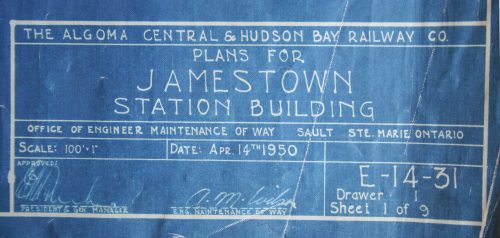
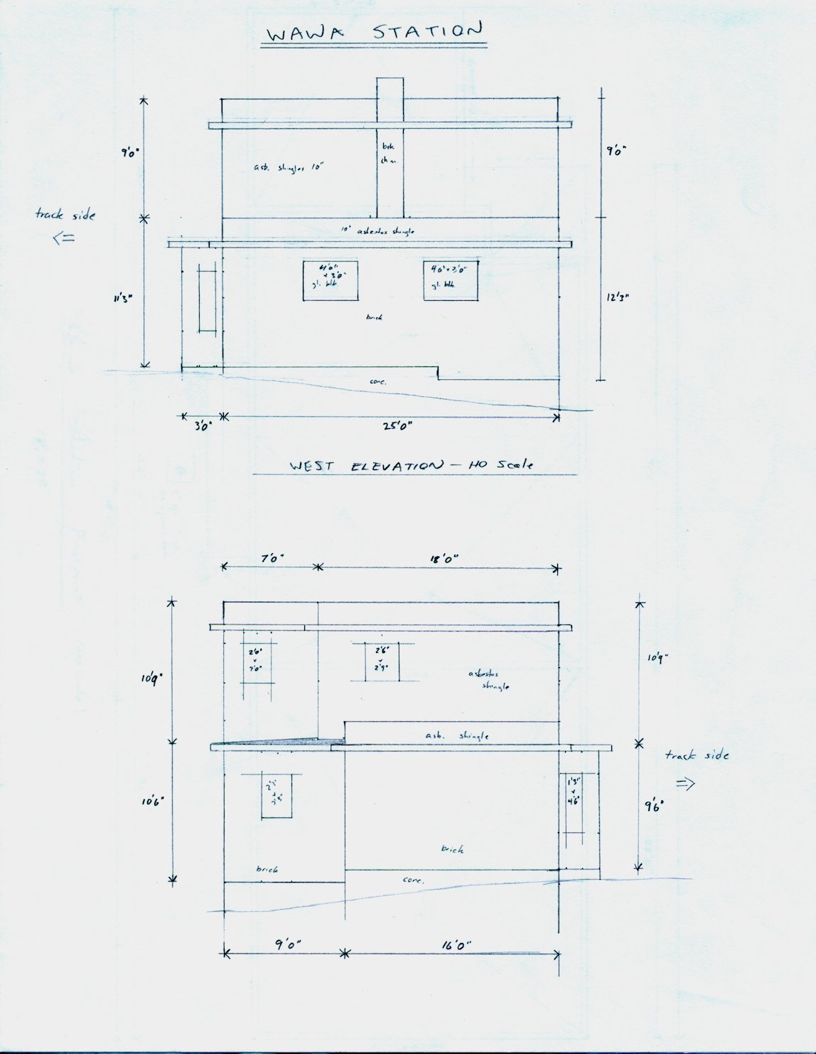
The original architectural blueprint for Jamestown (Wawa) station survive in the collection of the Sault Ste. Marie Public Library Archives.
The plans show a two story building with an overall footprint of 78 by 25 feet, with a 28′ baggage/express wing on the west side and 35′ long second story for the station agent’s living space located above the main part of the station. The interesting part of the design is the cut corners on the public waiting room end of the building, making it not quite a simple rectangular building.
The lower story is brick, up to the lower overhanging eaves (not sure of the technical term for this type of decorative overhang), and wood-frame with asbestos shingles above the overhang and for the second story.
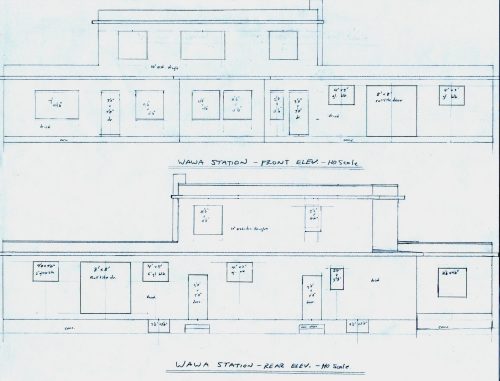
My HO scale front & back elevation drawings to lay things out to scale and plan the build before putting blade to plastic.
The first step in the project was of course to convert the images I took of the original plans into my own HO scale drawings in order to lay out the overall dimensions and locations of doors, windows, etc. on paper before I start cutting plastic and wasting material. I spent some time working on figuring out the drawings from the various images of the original plans this fall, until I had HO scale elevation drawings of all four sides and a top-down drawing of the roof/building footprint. With the scale drawings in hand, I could begin to transfer the measurements to plastic and start cutting out walls.
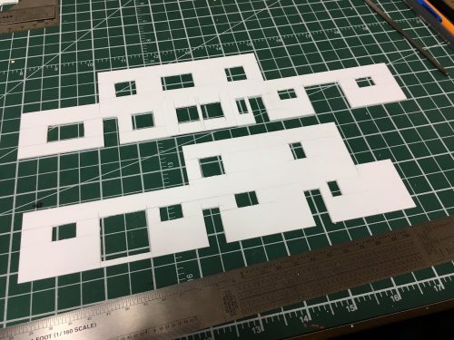
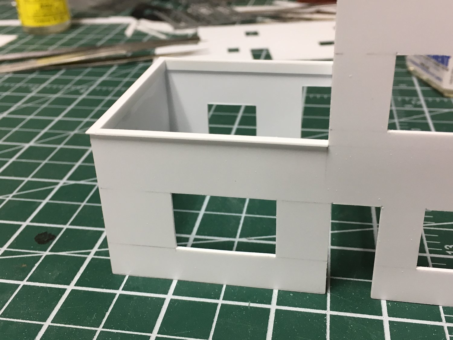
Front and rear walls with window and door openings rough cut out and ready for cleanup.
All of the wall pieces were cut from .040″ plain styrene sheet, with door and window openings carefully measured, cut out and filed clean.

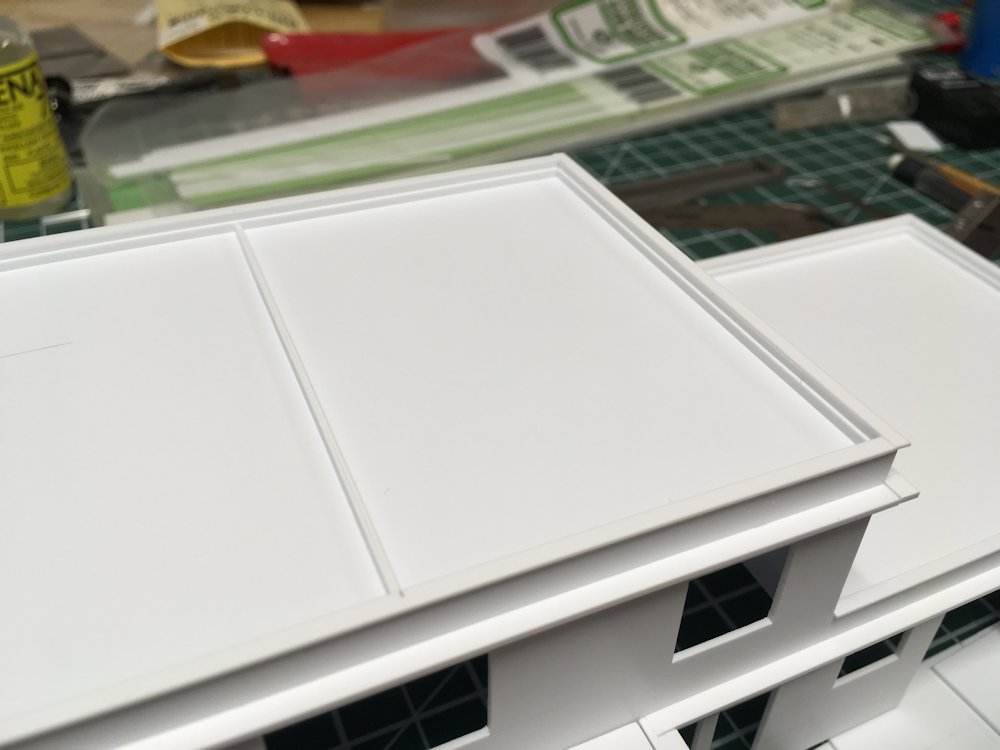
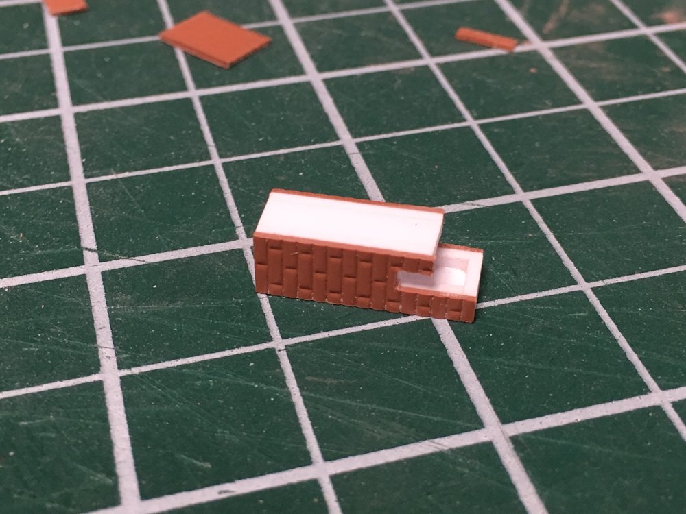
Detail of wall cap over passenger waiting room wing.
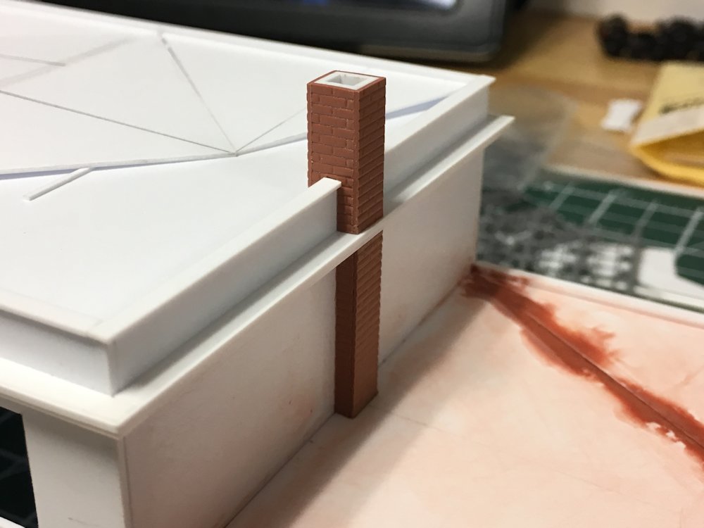
Above we see a detail of the treatment of the top of the walls. The architectural plans show the upper walls to be constructed of 2×6 framing. The very top of the wall is capped with a standard 2×6 header and then an overhanging 2×8 header above that, capped with copper flashing.
To represent this, and also to set up for the next step in constructing the recessed roof, I installed 2×10 strip around the inside of the tops of the walls, to bring the thickness of the top of the wall to near 6 scale inches and provide a proper depth to install the plastic sheet for the roof substrate. (More to come on roofing in a future post…)
Then the top of the wall was capped all around with a scale 2×8 strip to create the slight overhang at the top of the wall.

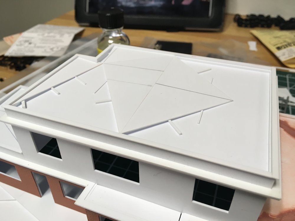
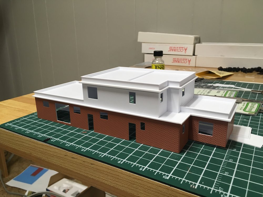
Basic form assembly complete, track side.
In the last two photos we see the basic assembly of the walls and roofing base completed, forming the basic structure.
There’s still a long ways to go on completing and detailing this structure, but with the walls and basic roof substrate assembled, it’s definitely starting to look like something!

Basic form assembly complete, street side.
So there it is so far. Stay tuned for more.
Note: if you use facebook, there are some additional images from this build in an album on the facebook page I have there tied to this site. You can find some additional project photos and other bonus materials shared there in addition to the regular blog post links.