Scratchbuilt underframes for 36′ boxcar bunk cars

I’ve been cycling through a few different projects on the workbench lately, including updating a few older projects. One of which is this set of old bunk cars rebuilt from 36′ wooden boxcars from the turn of the century. I started on the first pair last year, building up the bodies, adding basic styrene floors and also adding a third modernized car to the collection. I never finished detailing the underframes though and the project rotated to the side as other projects like Wawa station took the forefront this winter.

As I work through various smaller projects, I decided it was time to finish detailing the brake system on the underframes and move these projects a bit closer to completion. The main underframe is of course scratchbuilt from a floor of .040″ styrene sheet and the bolsters, main sill and braces built up from various sizes of styrene strip. I also scratchbuilt the coupler pockets right into the frame with a styrene strip box and a piece of .125″ O.D. tube for the mounting point, securely welded in place with styrene cement and tapped for a 2-56 mounting screw.

(I ended up locating the mounting point a bit far back, not accounting properly for the full thickness of the end sill on the body, but a long-shank Kadee coupler compensated for that, and having the mounting point a bit farther from the edge of the floor sheet is probably more stable.)

The truck bolsters are also built up from various pieces of strip and sheet, with a solid block formed from a stack of styrene pieces drilled and tapped for a 2-56 to mount the truck.

Brake details were added using a Tichy K brake detail set and brass wire for the rodding. It’s not a “contest-level” brake rigging system, but it gives approximately the right impression and shows an appropriate level of rigging detail for a track-level side view.

Work Car Wednesday #9

ACR From Blair 026

AC 10634/10365 is a twin unit articulated set (each half with its own number), converted from a twin unit coach originally built for the Southern Pacific Railroad for the famous Daylight passenger train. In the early 1970s the Algoma Central acquired at least half a dozen of these sets from SP, with a few being reconditioned and put into active passenger service, and a few others were converted into bunk cars for work service (or some of the former were later retired and converted).

According to my roster notes, 10634-10635 is possibly formerly AC 454-455 (may not have actually operated in service under those numbers, but the passenger series allowed holes for all these sets), ex-SP 2453-2454, ex-T&NO 506-507, and in its latest configuration shown here was a kitchen/diner (10634) and sleeper (10635) set.

ACR From Blair 025

Note the interesting truck design, original to these cars.

Both photos courtesy of Blair Smith, at Steelton Yard (Sault Ste. Marie) ~1997.

36′ Wooden Box Bunk Cars

Like every railway, especially those with extensive trackage through remote areas, the Algoma Central rostered a number of bunk cars to use as crew cabins for work crews working on construction or maintenance projects. Many of these cars are customized and home built for specific needs, usually from retired passenger or freight equipment.

The Algoma Central had a number of such cars converted from their old 36′ boxcars originally built in the early 20th century. There appeared to be a number of these in the 10600-10620 range, with a few others scattered elsewhere in the 10000 series work car numbering. A few of these cars were still in service in the early 1980s although starting to be replaced by pre-fabricated bunk units on flatcars (some of which reused the same numbers), and hoistman’s bunk car 10607 was even still in service in the late 1990s at Steelton yard.

AC_10608_Steelton_9_24_1983

Engineman’s bunk car AC 10608 (above, Ted Ellis photo September 24, 1983) is a good example of the typical configuration of the ACR’s bunk car conversions from the old 36′ boxcars; although from the photos I’ve collected of about 4 or 5 different examples of these cars each one is slightly different from each other in the specific details.

Since I’ve been working on a few crane support cars, I’ve also wanted to have that old hoistman’s bunk car (AC 10607) to match up with the crane equipment set (also, that particular car was repainted in a VERY eye-catching bright yellow in the early 1980s). And if I was going to build one, I was going to at least build a second one.

I actually started these around Christmas, but during January and February I basically did absolutely no modelling as I was working on some home improvement projects. However with some of the work out of the way, lately I’ve been able to dive into this project again and make some progress on this pair of bodies.

IMG_6895

(Left/rear AC 10608 Engineman’s bunk, right/front AC 10607 Hoistman’s bunk)

Each of these two cars are based off of specific prototype photos to match the subtly different details of the cars. (In this case, primarily the end doors on 10607, and differences in ladder details (still to come). Otherwise, the side door and window arrangements on these particular two cars are virtually identical, although other cars had some variations.)

The bodies are fairly straightforward, being built from .040″ scribed styrene sheet. The roofs so far are plain styrene sheet with some internal bracing to maintain the proper shape along the length of the car with some scale 1×8 for the fascia strip along the top of the body at the eaves.

091

The windows were definitely the most involved and time-consuming part of the project so far. Not having anything that would match both the small windows and larger windows by the doors (I probably could have used some Tichy windows for the smaller ones but nothing for the larger windows) I scratchbuilt all the windows entirely from styrene strip for a consistent look. The single small window shown above is 12 individual pieces of styrene strip including the window sashes and outer frame.

After cutting a scale 24″x24″ opening for the window, the outside of the window was trimmed with scale 1×4″ strip (with a piece of scale 2×3″ for the thicker horizontal sill). The inner frame (sash) of the window was made up of individual .030″x.030″ strips and the window mullions were painstakingly assembled by three pieces of .020x.020″ strip carefully cut and filed to fit exactly in the opening. (An exercise in patience and precision if there ever was one.)

This completes some of the major work on the body however. There is some additional detailing to do, and the doors need to be fashioned and all the ladders/grab irons added to complete the body details and then the roof and underframe will need to be completed yet. I’m looking forward to getting these a bit more detailed and sitting on trucks. I think some of these cars will come together into an interesting looking collection of old cars for a work train at Hawk Junction.

Gondola Details and Dimensional Information

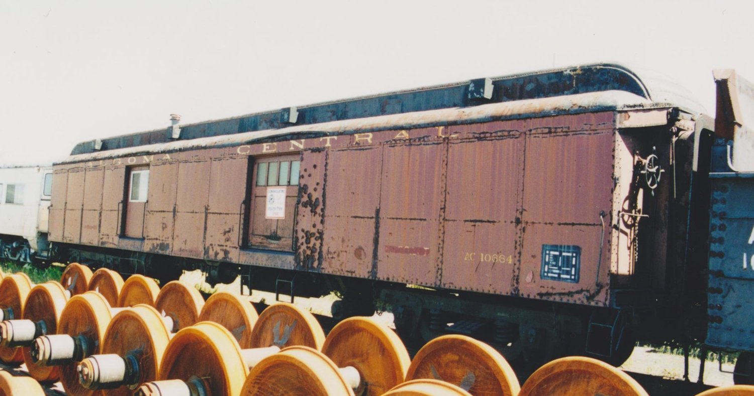
I had some requests for some more details on the dimensions and parts used in the scratch build of these two gondolas, so I’ve scanned my rough sketches for the post spacings and overall dimensions, and will attempt to provide some further details of specific measurements and strip sizes below.

I posted a scan of my scale drawing that I used as my official guide in my previous post, here are the rough sketches with a few more spacing dimensions jotted down.

ac0027

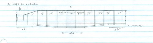
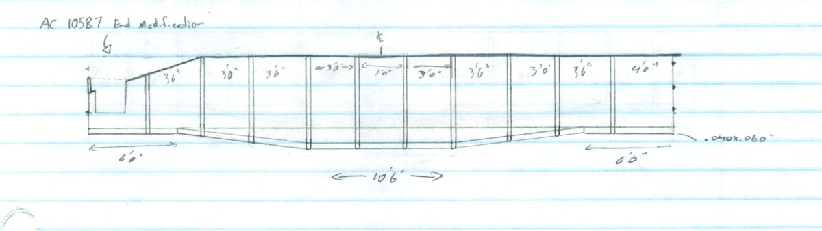
AC 4601-4803 rib spacing sketch, not to scale. (Click on image to enlarge)

ac0028

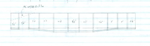
AC 4804-4850 rib spacing sketch, not to scale.

Also, for reference, here are actual dimensions from a 1960s Official Railway Equipment Register for the two series:

4601-4603 4804-4850
I.L. 39’5″ 40’10”
I.W. 8’11” 9’0″
I.H. 4’0″ 4’0″
O.L. 40’0″ 41’8″
Ex.W. 9’9″ 9’10”
Ex.H. 7’11”

Sides

Height of the side pieces (cut from .020′ sheet) is five scale feet, even. Overall length of the sides is 40′ for the 4601-4803 cars or 41′ for the 4804-4850 cars. (This probably shortens the inside length a little, but the scale foot difference and the different rib spacing makes a pretty good difference between the cars.)

For boom cars 10587 (ex 4601-4803) or 10588 (ex 4804-4850) the angled cut out reduces the end height by 2’6″ and runs in 7’9″ from the end.

Top chord along the top edge is .010x.080″ strip.

Drop Sills

For the drop side reinforcement, I cut the pieces from .040’x.060′ strip (.060′ in the vertical direction). I started the drop 6′ in from the end on both cars. The horizontal drop portion is 10’6″ on the 4601-4803 cars or 13’6″ on the 4804-4850 cars, centred. The bottom edge of the fishbelly is 1’6″ below the edge of the side sheet.

Ribs

The prototype cars actually appear to have ribs that are a Z angle, which isn’t too hard to custom fabricate (I’ve done it before), except for the rounded off bottom bit. I ended up just making them a little more solid on this pair of cars, using plain .040x.040′ square strip on a .010x.060′ flange piece. The square stock is not centred on the flange, but aligned to one edge. Note when installing the ribs that the flange edge faces away from the centre of the car. (i.e. the “open” end of the Z would face the centreline of the car.

The height of the rib pieces then is of course cut to length – 5’6″ near the car ends, 6’6″ in the centre and cut to size when placed over the angled part of the drop.

See above diagrams for spacing.

Corners and Ends

Ends are .020″ styrene sheet again like the sides, and 9 scale feet wide.

The corners are trimmed up with .010x.080″ strip. Rivet decals will be applied later to the corner strips and at places along the bottom edge of the side.

The end bracing is .010x.060″ strip applied flat to the end sheet, and a .010x.030″ strip applied on edge on top of that to form the distinctive T section stiffening ribs.

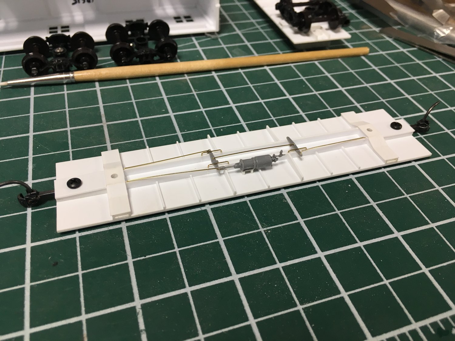
Floor and Underframe

The styrene floor is also .020 sheet, cut to fit within the assembled body sides and ends. I used .080 spacer strips to recess it from the bottom edge, and I’m planning to apply a wood floor with 1x? strip after the body is painted.

The bolsters are built up from styrene to an overall depth of .165″ for the truck mounting following similar commercial parts. This seems to be about the right height, although may still require an adjustment washer. (I’m really hoping it doesn’t end up too far off.)

I used a piece of lead sheet for the weight (we had some old leftover flashing at the club – I’m not sure how readily available the lead sheet is still these days but there must be somewhere to find it) and then built up the underframe on top of that. The centre sills are .040 sheet and should roughly match the profile of the sides. The rest is all cut to fit to give an impression of the framework.

Lots more to be done yet, but I think that covers the current build progress so far. Hope this is of interest or help to those curious. This is an interesting build so far, and it’s been fun to have some questions and feedback.