(Click on images for larger versions)


(Click on images for larger versions)
In the late 1940s, the Algoma Central Railway’s car shops rebuilt 250 old 40′ flatcars into gondolas by fabricating new bodies on existing underframes. This fleet comprised two unique series: AC 4601-4803, 203 cars with 39’5″ inside length rebuilt from late 1946 to late 1947; and AC 4804-4850, 47 cars with 40’10” inside length rebuilt in mid-1948. In addition to the extra one foot of length, the latter cars can be visually identified from the former by a different spacing of the side ribs. These cars lasted in revenue service into the 1970s by which time most of them were retired, but several cars remained in work service for a longer time.
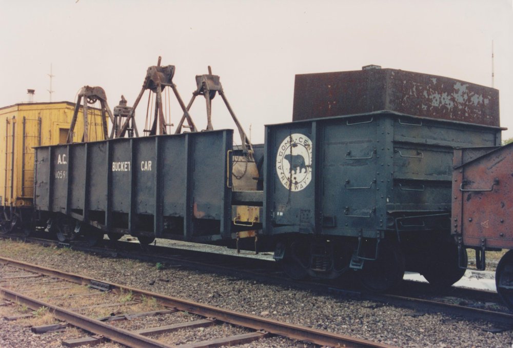
AC 10591, ex-4601-4803 series gondola in work service as a bucket car for the railway’s diesel host in the early 1990s. Photo courtesy Blair Smith.
As “new”, the cars were painted in a simple black scheme with what is probably the first usage of the black bear logo on freight cars. The logo was ringed in red, and a partial example of a 4601-4803 series car in original paint can be seen on the left edge of this 1956 photo. (Another 350 brand-new 48’6″ gondolas were also acquired in September 1947 from National Steel Car in the AC 3501-3850 series, and also painted this way when new.) Meanwhile, this 1979 photo of AC 4849 shows the paint scheme they wore in the 1960s-1970s.
Obviously such a strikingly unique car with those open fish-belly side sill reinforcements is just begging to be modeled, and this home-built car is just the thing to help capture the character of the railway. To that end, I’ve used known overall dimensions from ORER listings (thanks to Railwire user “Kisatchie” for looking up some numbers for me as my oldest copy is from 1975 which no longer includes either of these series) and photographs to try to work out some sketches and a “reasonably close” scale drawing.
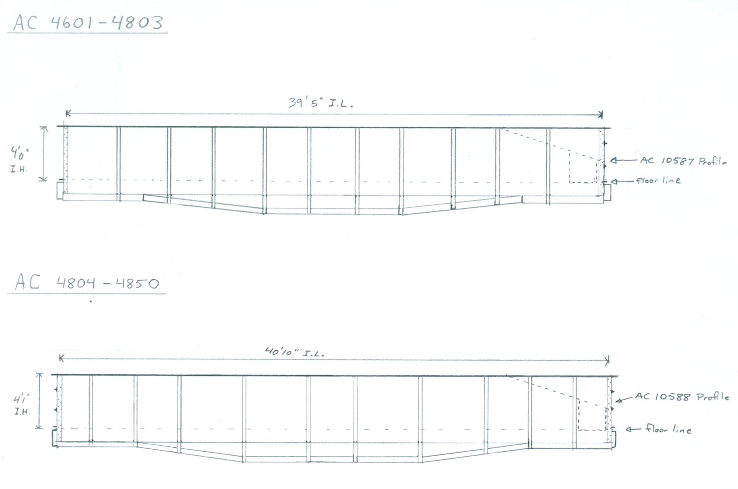
Side elevation drawings comparing AC 4601-4803 and 4804-4850 series gondolas.
Over the last couple of weeks I’ve been slowly working on a pair of these cars – one each of each type. Both will become support cars for my diesel crane: bucket car 10591 (ex-4601-4803) and boom car 10588 (ex-4804-4850).

In progress model of 4601-4803 series car.
The sides are .020″ styrene, with side posts consisting of a .040x.040″ strip on a .010x.060″ bottom flange – although it appears the ribs on the prototype car are actually a Z-angle. The drop side sill is .040x.060″ strip and the top chord is .010x.080″ strip.
Stay tuned for more progress on what should be a very unique pair of cars.
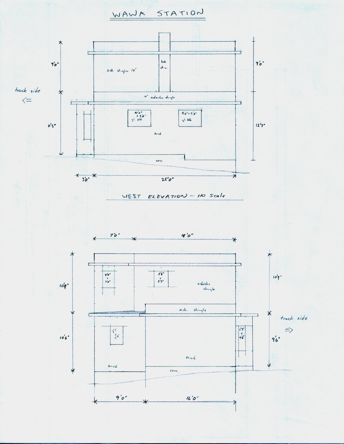
A railroad requires a lot of regular maintenance to keep the operations running smoothly. And in the old days prior to reliable automotive transport and modern track maintenance machines, a small local maintenance crew would have been responsible for inspecting and maintaining a given section of track of a few miles. The section bunkhouse (and related nearby sheds for storing maintenance supplies, tools and other materiel) served as the home for the local “section” foreman. (These track maintenance workers responsible for a section of railway were sometimes called sectionmen.) With the advent of more mechanized forms of track maintenance, fewer workers could maintain much larger stretches of railway, so manpower needs were reduced, and the section houses closed. Most section houses are now long gone from the railways, but several of the old Algoma Central section houses still stand today. Some stand derelict and abandoned but some (particularly the remaining ones closer to the south end of the railway) are now privately owned camps and cabins.
Most railways had standard designs for common structures along the line like section bunkhouses. Here, the Algoma Central was no exception. The ACR’s standard 2 bedroom section house was a 2-story wood-frame structure with the gable ends aligned perpendicular to the tracks, a covered porch at the front and a 1-story kitchen annex at the rear. An original drawing from the Algoma Central’s files of a 1951 version of the standard plan exists in the collection of the Sault Ste. Marie Public Library’s archives.

Excerpt from ACR drawing # C-5-4 (Standard Section House). Collection of Sault Ste. Marie Public Library Archives.
The drawing shows a main structure with and 18’ x 22’ footprint and a 14’ x 14’ kitchen attached to the rear. The main floor features a living and dining area and the upstairs has two equally sized bedrooms. The section houses built along the line tended to vary slightly from the actual drawing though, and a close look at the drawing shows that it’s been revised a couple times and you can see where pencil marks for locations of doors and windows around the kitchen annex have been shifted around on the drawing.

Main floor plan of standard section house.
Excerpt from ACR drawing # C-5-4 (Standard Section House). Collection of Sault Ste. Marie Public Library Archives.
However as mentioned, as new houses were built or rebuilt over the years, the details of each individual section house tended to vary slightly, and I don’t think a single one of the section houses of which I have photographs matches the drawing exactly in every detail. The dimensions of the main part of the structure stayed consistent, but window arrangements could vary slightly from location to location, and sometimes the internal floor plan is mirror imaged from the “standard” plan.
The standard drawings also show a 1/3 roof pitch on the main structure, which some existing houses appear to match (Northland and Franz) but the majority seem to have a much steeper roof pitch, so there’s at least two variations here.
The kitchen annex was where the most variation tended to be; varying in size and particularly in window and door arrangements, much more than the main part of the structure. (It appears that for some older section houses, the annex was actually added later.)

Agawa section. September 30, 2013. Chris vanderHeide photo.
This abandoned but still-standing section house at Agawa (Mile 130.9) is pretty close to the standard drawing (other than some window locations on the kitchen and steeper roof pitch) and illustrates the typical style and finish quite nicely, with an asphalt shingled roof, wide veranda porch on the front of the structure and milled board siding (what Evergreen would call “novelty siding” in their line of textured styrene sheet products for model scratchbuilding).

Mashkode section. July 28, 2014. Chris vanderHeide photo.
At Mashkode (Mile 56.2), now a privately owned cottage but more or less unaltered from its previous appearance, we can see the bunkhouse in context of the other outbuildings that would typically accompany the sectionhouse: a small storage shed, and an outhouse.
Not visible, but also would have typically been part of the collection of structures for a section would be a track speeder and tool storage shed near the tracks and in some locations, as the main structure was only a 2 bedroom affair, additional small one man bunk cabins.

Main floor plan of Wyborn section house.
Excerpt from ACR drawing # E-23-4 (Wyborn Section House). Collection of Sault Ste. Marie Public Library Archives.
Often located many dozens of miles from any sort of recognizable community, very few of these section houses were located anywhere near any municipal sources of running water or electricity. Wyborn (Mile 294.1) is a notable exception; the section house here was located within the city of Hearst and an original drawing of this section house also exists in the Sault Ste. Marie Public Library Archives (dated 1937 but with a notation for a 1968 revision), and this drawing shows a full bath with tub and shower on the floor plan, as well as the location of the incoming electrical meter and breaker box (near the left side of the kitchen). This section house is also a little unusual in that instead of a full width veranda porch on the front, there is a simple peaked canopy just over the entry door, and the drawing specifies in this case aluminum siding.
And of course with many of the surviving former section houses on the line now in private ownership as camps and cottages, many of them have been rebuilt to some extent or another, further changing their appearance from the standard plans.

HO scale scratchbuilt model of Franz section house by Chris vanderHeide.
Several years ago, I attempted to build this model of the section house at Franz, scaling it from photos. While the proportions have always felt relatively close, I’ve felt that it ended up being oversize. The dimensions on the original railway drawings confirm that the model is approximately 10% overscale. (I got too-large windows and sort of proportionally scaled things off that comparison.) It’s a pretty good representation, but now that I have access to the proper dimensions in the official drawings, I can do a much better job of constructing a version with much more accurate dimensions.
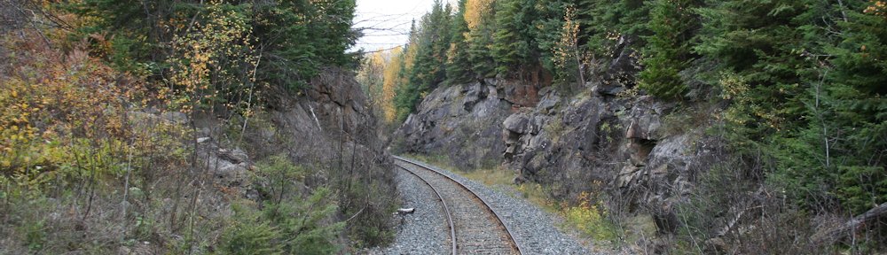
So this evening I got a little bored and looking through and organizing some of my reference photos and ended up studying some of the photos from the Oba Lake area and specifically of the long wooden trestles that cut directly across several bays of the lake.
I also have several images of a 1951 AC&HB drawing for a standard timber trestle from the Sault Public Library Archives, and I started looking at this in detail and comparing it to the Oba Lake photos, figuring out the construction and trying to estimate the height of the structure. Looking at the timbers in the abutment at the end of one bridge, the height from the top of the bottom sill (which rests on pilings right around the waterline) seemed to be roughly 7-8 feet. Subtracting the thicknesses of the ties, heavy stringers, and the bent cap and sill, I estimated an approximate height of about 4′ for the height of the vertical members in the trestle bent and started sketching, and before long I had drawn an exact scale section drawing of a representative bent, based on this height.
So I thought I’d throw this up here. Since I don’t have a layout space, it’ll be a long time before I could ever actually model a representation of this, but maybe someone else finds this useful, even if you just enjoy the details of trestle construction. Since the height is estimated, this may not be exact, but seems to work out fairly well.


All timber sizes, lengths and spacing are taken directly from the standard drawing except for the vertical member and the bottom sill (lengths estimated) and the diagonal braces of course adjust to fit.
I drew the side elevation with cross bracing every other span similar to the standard drawing, but due to the low height of the trestles over Oba Lake, they don’t appear to actually have any, so these should be left out. Unfortunately side photos of these bridges are almost impossible to find thanks to the remoteness of the location, but close inspection of the next photo below shows that there isn’t any X-bracing on the outside of the trestle. This doesn’t necessarily rule out any additional hidden internal bracing between the bents though.
The water level was high when I rode the Tour of the Line to Hearst and took these photos at the Oba Lake trestles, so the lower sills of the bents are just barely even poking out of the water. I’ve come across and saved some other photos from online with lower water levels though, where the sills are at least a foot above the waterline and you can see that they rest on the tops of the actual pilings driven into the lake bottom. Also, the longest bridge was replaced sometime in the late 1990s or early 2000s and the pilings for the original bridge can still be seen off to the side, although with the high water level on my trip they were below the surface of the water – you could see them from the rear of the train but they don’t show in my photos.

If you look carefully at the above photo, taken of the southernmost bridge at mile 211.9, one can pick out most of the features including the extended length of the sills almost under water, the heavy bent caps, the ends of the angles sway braces bolted to the cap and the horizontal plank just above the sills stabilizing the structure.
At the north end of the replaced bridge at mile 212.7, one of the original timber sills for the old trestle still remains and is visible right at the waterline, and you can see the notches in it where the vertical 12″x12″ posts once sat.
