I’ve been taking advantage of free time over the long weekend (“Family Day” civic holiday in Ontario today) to tackle the next major construction piece of the project – the “flat” roof.
In actuality, the roof is not quite flat in order to allow rainwater to properly run and drain and not build up on the roof and cause rot, leaks or other problems.
The architectural blueprints show how the roof slopes away from the edges to drains. On the upper roof over the second story a 2×6 board on edge establishes the height of the roof at the edge of the roof, sloping down to “zero” at the central drain. Construction details are: 7/8″ sheathing flat on the second story roof/ceiling joists, 2×6 support at perimeter (with successively cut down supports to allow roof to slope), 7/8″ top sheathing and finished with a tar and gravel surface.
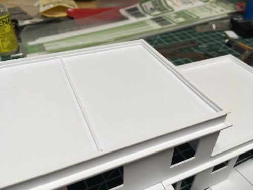
This first photo (above) shows the styrene 2×6 strip added all the way around the perimeter of the roof. The second story roof was actually divided into two drainage areas, so an additional pair of support 2×6 strips run down the centre of the roof dividing it into half.
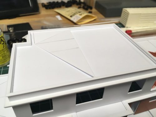
Roof sections made of .020″ thick styrene sheet being added.
Short pieces of .020, .040 and .060 styrene strip help support and reinforce the joints between roof sheets.
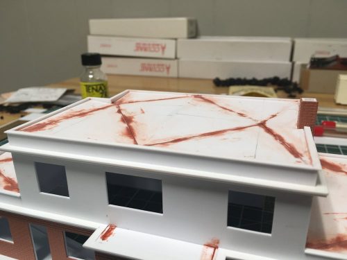
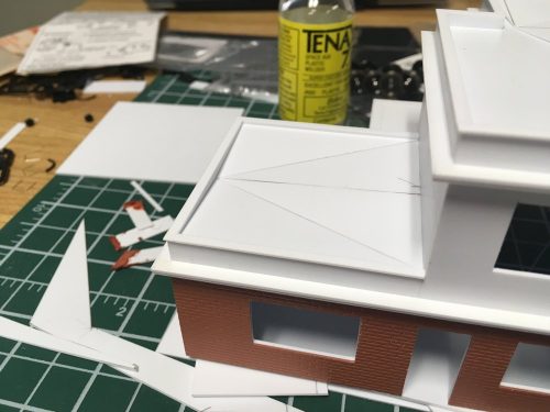
Roof sheets completed, and joints touched up with spot putty. The slope effect ends up actually being pretty subtle overall, but is obvious in the indented corner on the second story, as well as over the passenger waiting room wing where the drain is at the edge of the roof and everything slopes down to this point. On the large open area of the baggage room where the entire roof slopes to a central point, the effect is difficult to see without laying a straightedge on the wall caps, but the modeler knows it’s there!
The final finish work to the roof will involve a bit of trimming around the chimney and wall caps, and the final surface will be a representation of the bonded tar-and-gravel surface of the prototype. This however, will likely be one of the last steps after painting the rest of the structure.


Congratulation for taking into account architectural details such as drainage bassins and flashing on the roof perimeter. Too often overlooked… but giving so much character to scale structures.
Having the original blueprints showing this detail definitely helped – otherwise I might not have thought of it properly especially lacking photos showing the roof.
Chris
Bonded tar and gravel, and graveled roof structures in general, can be modeled using sandpaper as the surface. A new building at my work site was graveled, and I guesstimated that something in the 2-300 grit range would be a good representation.
Worth a look, anyway, given the price of a sheet of sandpaper.