
In a previous post, we looked at data, stencils and lettering that can update or firmly root a car’s appearance to a 1970s or newer time frame. Here we’ll look at some of the concurrent physical changes to freight car hardware (and rules regarding the same) that will also help indicate the modeled time frame.
Running Boards, Ladders, and Handbrakes

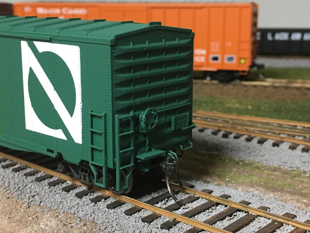
Model of a modern (1974-built) boxcar built with low ladders and no running boards (roofwalk). The “ribbed” outside-post construction of this car is also a post-1960s signature.
The earliest railroad boxcars featured handbrakes that were operated via means of a wheel attached to a vertically-mounted brake staff that would be operated by a brakeman walking on wooden running boards down the centre of the car’s roof.
While automatic air brake technology was introduced and improved during the late 1800s, this arrangement stuck around, with the handbrake to tie down a parked car still located at the top of the car end, and running boards (later made of steel instead of wood) to allow brakemen to move down a cut of cars to set (or release) multiple hand brakes.
The first major change in rules regarding running boards came in 1945 when wood walkways outlawed on new cars. New cars were to feature expanded metal running boards, but the wood walkways were generally not replaced on older cars. (Obviously metal running boards would have existed before this but I don’t have any “first” dates of adoption.)
The most significant change came in 1966 when the rules were changed to no longer require running boards. New cars ordered after 4/66 or delivered after 10/66 were required to be built without running boards and low-mounted handbrakes. Running boards also began to be removed from cars, with the original target date for completion being 1974, but full compliance lagged behind a bit. By 1982 walkways were banned on boxcars and reefers in interchange service in the US.
Older 1940s built boxcar that has been upgraded and modernized to remove running boards (although the former supports are very much in evidence) and cut down ladders. On this car the brake gear has also been lowered, however on many cars the brake wheel was left in its original position, with full height ladders remaining on the “B” end corners to reach the handbrake.
Journal Bearings

50 ton truck with plain bearings (left) vs modern 100 ton truck with roller bearings (right)
Railroad car axle bearings came in two distinct “flavours”. The old style featured a solid axle end which turned on brass bearing inserts inside an oil-filled journal box cast as part of the truck. This is what is known in the trade as a “plain” bearing – sometimes also referred to as “friction” bearings, although only after roller bearings became common. Modern railway axles use a self-contained, sealed package of roller bearings
Some lists of dates show the first usage of roller bearings on motor cars and some steam engines and freight cars in 1923 and first roller bearing on passenger equipment around 1926.
As far as I can tell from trolling through several lists of important dates, the first significant regulations about roller bearing journals came in the 1970s, with roller bearings required for all cars with 6 1/2″ by 11″ journals in 1972 and roller bearings required for all cars with axle loading greater than 55,000 lbs in 1974. (Basically, larger 90-100+ ton capacity cars being built then.)
By 1991 all cars in hazardous materials service must be equipped with roller bearings and may not be equipped with plain bearings and in 1995 plain bearings were banned from interchange entirely.
Trucks
The earliest freight car trucks were wood beam trucks with a heavy wood beam upper member and cast iron or steel journal boxes, spring hangers, bracing and other hardware. By 1870 “archbar” truck frames fashioned from heavy steel bar bolted together started replacing wood beam trucks as standard. Later trucks used various types of cast sideframes. Archbar trucks were banned from interchange service after July 1, 1940.
By 1958 all trucks applied to new cars were required to have AAR approved side frames with U-shaped castings and integral journal boxes. Cast truck side frames with T, I, or L shaped cross sections were prohibited under cars in interchange service.
Wheels
The last few changes are harder to note quickly from a distance as they’re underneath the car, but can still be seen in a side view.

Ribbed-back cast iron wheels (left) vs steel wheels (right)
Modelers may have noted that there are generally two styles of wheels available with some model trucks available (either as replacement trucks or included in some full kits or RTR models). Some wheels have a fancy-looking ribbed back appearance, while others have a profiled but plain back face such as the truck at top right in the photo. (Of course, some model wheelsets also have a completely smooth undetailed [inaccurate] flat-backed design….)
The ribbed back wheels represent older cast iron (not steel) wheels. Cast iron wheels were hardened in chilled water. To withstand this process the had ribbed backs. Steel wheels did not require or have these ribs.
As of January 1st, 1958 cast iron wheels were banned from new and rebuilt cars, From January 1st, 1964 no new cast iron wheels were allowed on existing cars, and from January 1st, 1968 all cast iron wheels were banned from interchange.
This is also a good place however to mention different sizes of wheels. Generally speaking, most older freight cars had used 33″ diameter wheels. However cars of 100 tons capacity or above rode on larger 36″ diameter wheels. Many modern trilevel autorack cars ride on low profile 28″ wheels. If you’re replacing wheels on your model freight cars and aren’t quite sure whether you should be using 33″ or 36″ wheels, take a look at the CAPY or LD LMT data lines below the car number. If those numbers are around 200,000 (lbs) or above, use 36″ wheels. Around 150,000 (lbs) is a 70-ton car likely with 33″ wheels.
Brake Systems

KC brake piping diagram
The first Westinghouse air brakes were patented in 1869.
In the early part of the 20th century, the common air brake systems in use on freight equipment (known as K or KC brakes) were a simplified affair where the brake cylinder, air reservoir and control valve were all combined as one unit. The more modern air brake system design (known as AB brake systems) that most people will be more familiar with are quite visibly different, with separate components for the brake piston, control valve, and a large air reservoir with separate halves for service [regular] and emergency brake applications.
In 1933 AB brakes were required on all new cars and the older K/KC brake systems were outlawed from interchange service in 1953.

AB brake piping diagram
Some good railroad timeline resource links:
http://www.bluford-shops.com/bluford_93_024.htm
http://www.hosam.com/grd/dates.html